Introducing PowerFlex File Services is an article that introduces PowerFlex File Services.
PowerFlex File Services was introduced in PowerFlex 4.0. This feature enabled file-based access via sharing protocols such as SMB (Server Message Block) and NFS (Network File System), expanding PowerFlex’s capabilities beyond block storage to include file storage functionalities.
The PowerFlex cluster can offer File Shares using the SMB and NFS protocols. Before providing these shares, a NAS Server must be running on the system. A NAS Server is a file server that supports the SMB, NFS, FTP, or a combination of these protocols to share data with host clients. It also catalogs, organizes, and optimizes read and write operations to the associated file systems. The following table provides definitions for some PowerFlex file terms:
| Term | Definition |
| PowerFlex File Services | A storage resource can be accessed through the file sharing protocols such as SMB or NFS. |
| PowerFlex File Node | A virtualized network-attached storage server that uses the SMB, NFS, FTP, and SFTP protocols to catalog, organize, and transfer files within file system shares and exports. PowerFlex file service is responsible for the configuration parameters on the set of file systems it serves. |
| NAS Server | A Virtual Data Mover which provides data services to users. |
| Virtual Data Mover (VDM) | A single point of access to a remote resource. |
| File System | A storage resource that can be accessed through the file sharing protocols such as SMB or NFS. |
| Network File System (NFS) | An access protocol that enables users to access files and folders on a network. NFS is typically used by Linux or UNIX hosts. |
| Server Message Block (SMB) | An access protocol that allows remote file data access from clients to hosts on a network. SMB is typically used in Microsoft Windows environments. |
| Snapshot | A point-in-time view of data stored on a storage resource. A user can recover files from a snapshot or restore a storage resource from a snapshot. |
Note: All details to deploy the PowerFlex File Services can be found in the following link:
https://dl.dell.com/content/manual33459856-dell-powerflex-4-5-x-install-and-upgrade-guide.pdf?language=en-us
Deploying the PowerFlex File Services
So, we will show all the necessary steps to deploy the File Services in a lab environment.
We have the PowerFlex version 4.5.2, and all PowerFlex Cluster components (MDM, SDS, SDC, File Node, etc) are virtual machines (VMs).
In this demonstration, we will use two File Nodes (two VMs) for the File Services.
Discover Resources
The first step is discovering both File Nodes as a resource in the PowerFlex Cluster. Go to the Resources menu –> Discover Resources:

In the “Identity Resources,” we need to specify the resource type and fill all necessary fields, as shown in the following picture.
Since we are not using a physical server, the resource type must be “Node (Software Management)”:

A mgmt job will be created and can be monitored under the “Events” menu:

After some time, we can see events showing that both resources were added successfully:
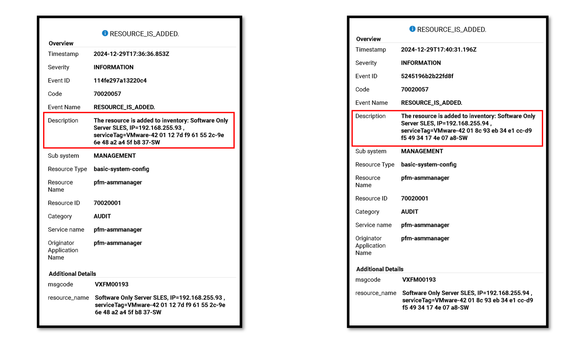
We could see both File Nodes under the Resources menu if the discover resource process was executed successfully. Look at the “Deployment Status” column. “Not in Use” means that the resource is not being used but is available in a resource group:

Create a PowerFlex File Template
Afterward, we must create a Template to deploy the PowerFlex File Services. Under the Lifecycle menu, select Templates. Click on the Sample Templates tab. In this tab, we can see all sample templates. Click on “PowerFlex-File- SW Only” –> More Actions –> Clone.
We will create a template clone from this sample:

Type the template name and template category, and click on Next to continue:

Under “Network Settings,” we must select each network to use on the new template.
Note: We must define the Networks before creating the template. Go to the Settings –> Networks to determine the Networks.

Under “PowerFlex Gateway Settings” we need to select the PowerFlex System:

Under the “Node Pool Settings,” we can maintain the default configuration (Global) and click on Finish to create the template:

When using a “custom node pool,” select this pool from the “Original Node Pool” option. A Node Pool is a logical container that groups one or more nodes that can be used to create resource pools.
Click on Finish to conclude the template creation!
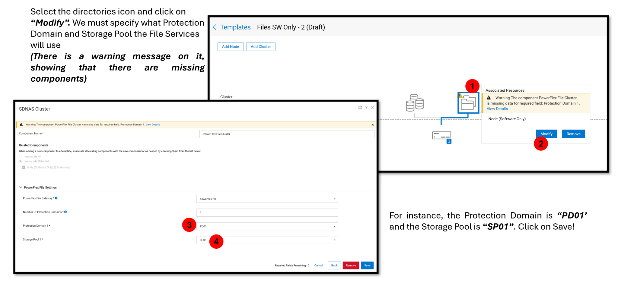
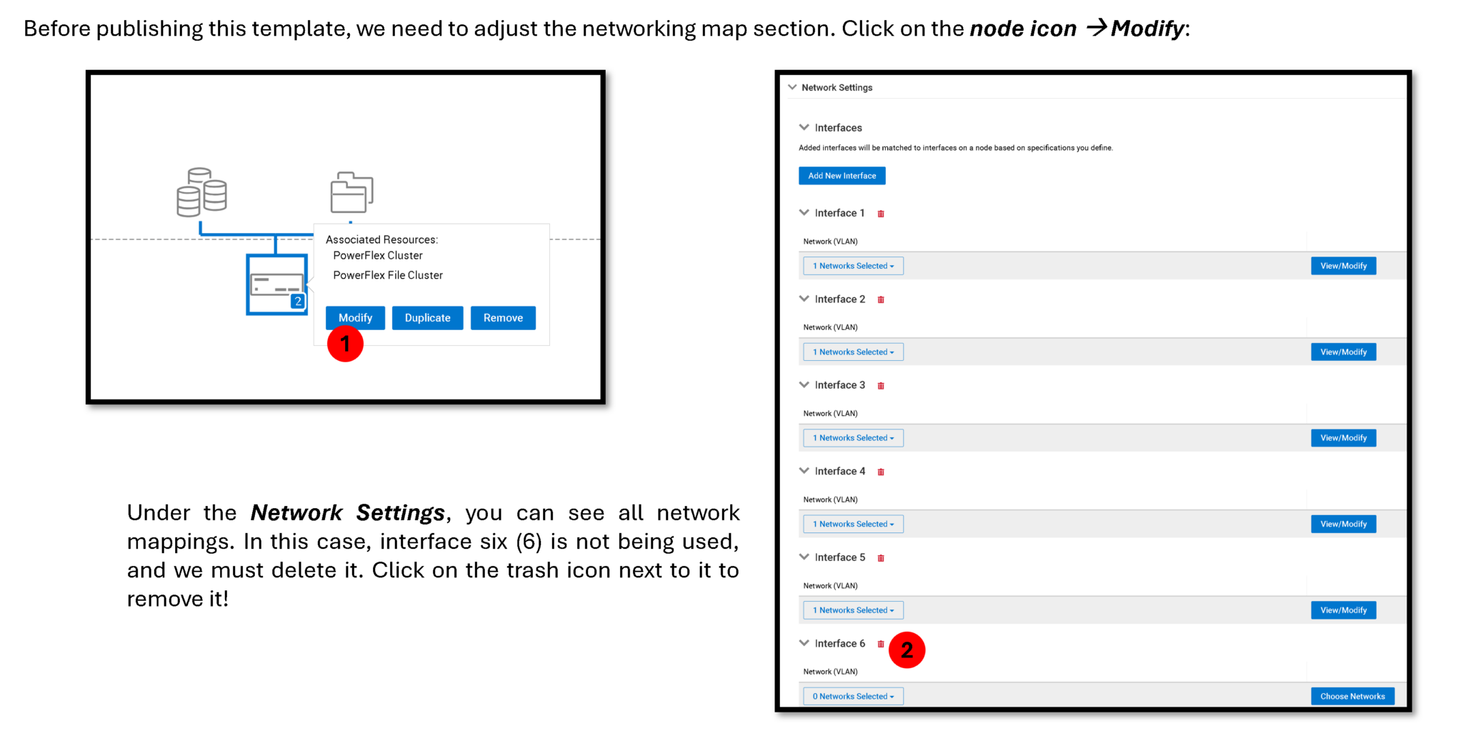
After making all the necessary changes under the new template, click on “Publish Template” to make it usable to deploy new resource groups from this template:

To deploy a new resource group from this template, click on “Deploy”:

Deploy a Resource Group
Select the published template under the Deploy Resource Group wizard and type the resource group name. Click on Next to continue:

Under the Deployment Settings, keep the default values and click on Next to continue:

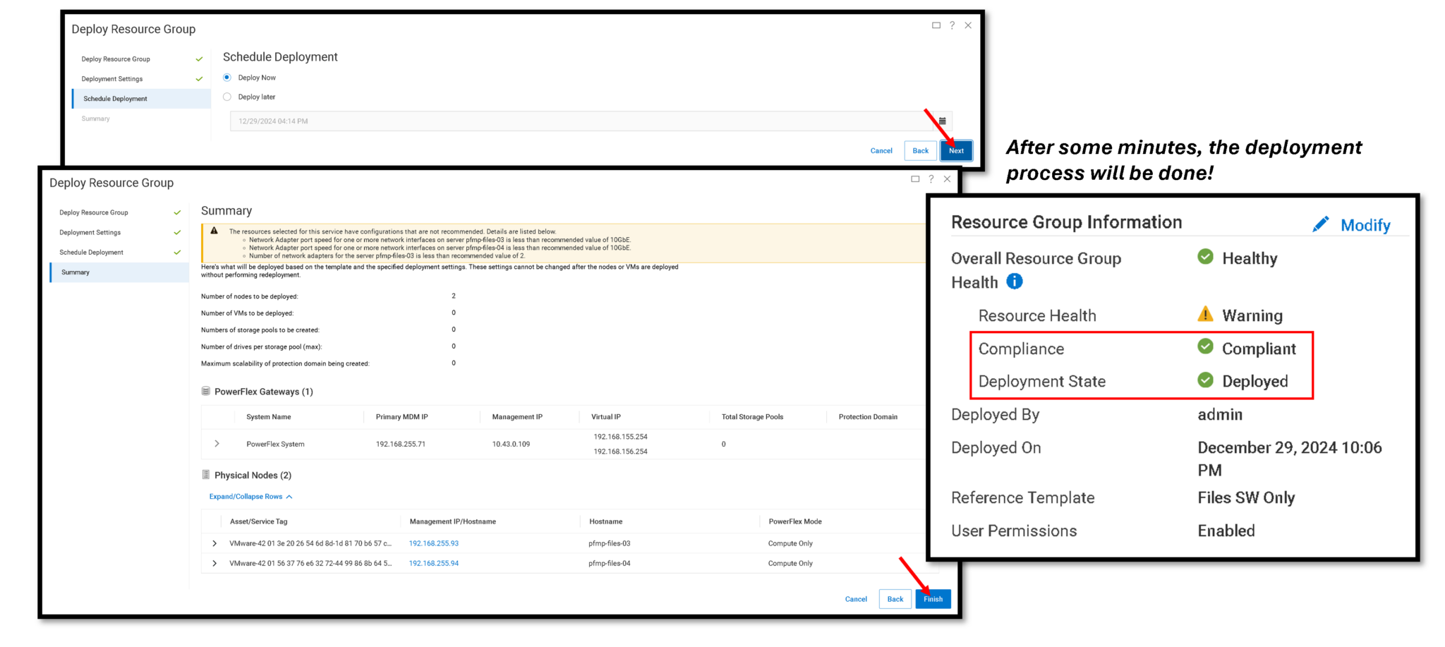
On the Resource Groups page, we can see the deployed Resource Group:

Creating a NAS Server
A NAS Server is a file server that supports the SMB, NFS, FTP, SFTP, or a combination of these protocols to share data with host clients. It also catalogs, organizes, and optimizes read and write operations to the associated file systems.
Access the PowerFlex UI –> File –> NAS Servers –> Create NAS Server:

The IP address 192.168.158.200 is from the File Node Management network.
This is the “File Server” IP address the clients will use to access the shares (SMB or NFS shares).
Enable the Protocol Type you please and click Next:

Under the “Windows Server Settings,” we join the NAS Server into our Active Directory Domain. If you don’t have an Active Directory Domain, you can create a standalone domain and follow with the configuration wizard. This step is necessary to enable SMB protocol support:

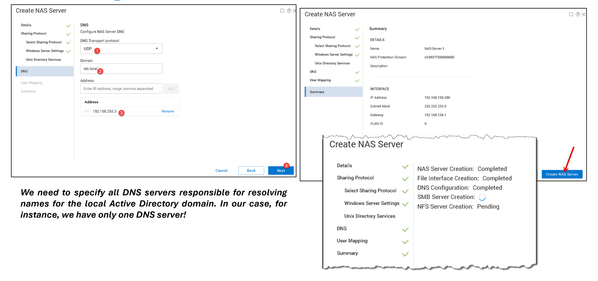
As we can see in the following picture, the NAS Server was created successfully!
Look at the “Primary Node” and “Secondary Node” details. The created NAS Server runs on both nodes:
— Node 1 is the primary node, and node 2 is the secondary node;
— This means that File Node 1 accepts all clients’ requests, and, in case of failure, File Node 2 will be used for it;
— Inside each File Node, there is a docker container (sdnas containter) responsible for hosting the NAS Server!

SDNAS container on the first File Node:

SDNAS container on the second File Node:

To see all NAS Server’s configurations and details, select the NAS Server and click on “View Details”:

Creating a File System
A File System represents a set of storage resources that provide network file storage. The storage system establishes a file system that Windows users or Linux/UNIX hosts can connect to and use for file-based storage. Users access a file system through its shares, drawing from the total storage allocated to the file system:

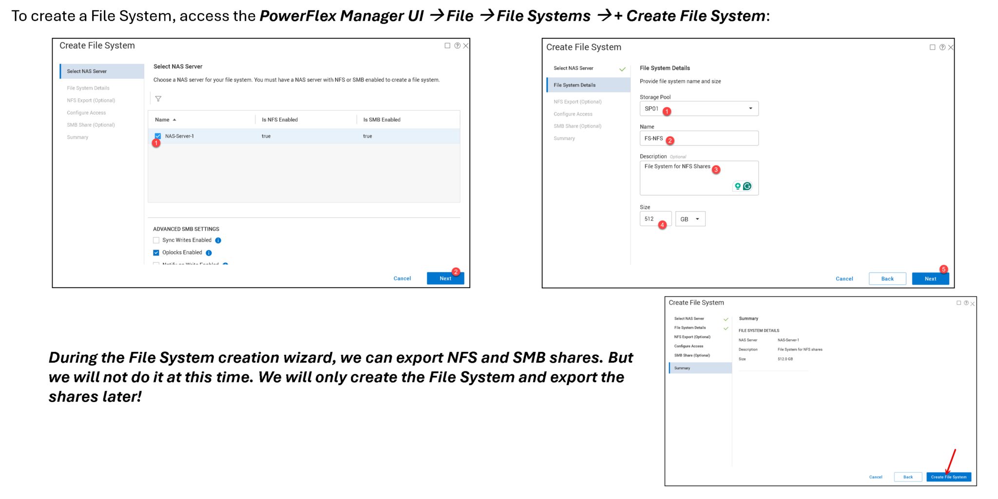
To check File Systems’ details and configurations, select the File System and click “View Details”:

On both File Nodes (node1 and node2), we can identify both volumes used by creating the File Systems:

To see all Volumes used by the File Services, go to the created Resource Group and click on “View All Settings”:


Creating an SMB Share
To create a SMB share, access the PowerFlex Manager UI –> Files –> SMB Shares –> + Create SMB Share:


Since our NAS Server is joined into the Active Directory, we will control the share access through Users and Groups of the Active Directory:

To adjust the SMB share permission, go to a Windows machine (joined at the AD domain), open the “mmc” and add the Shared Folders utility, pointing to the NAS Server, as we can see in the following pictures:


Adjust the share and file system (NTFS) permission as necessary. In this example, only all users from the Group “GG_SMB-IT” have full access to the “IT” SMB share:


Mounting the “IT” SMB share on a Windows machine:


Creating an NFS Share
To create a NFS share, access the PowerFlex Manager UI –> Files à NFS Exports –> + Create NFS Export:


Type the NFS Export name and description and click on “Create NFS Export”:
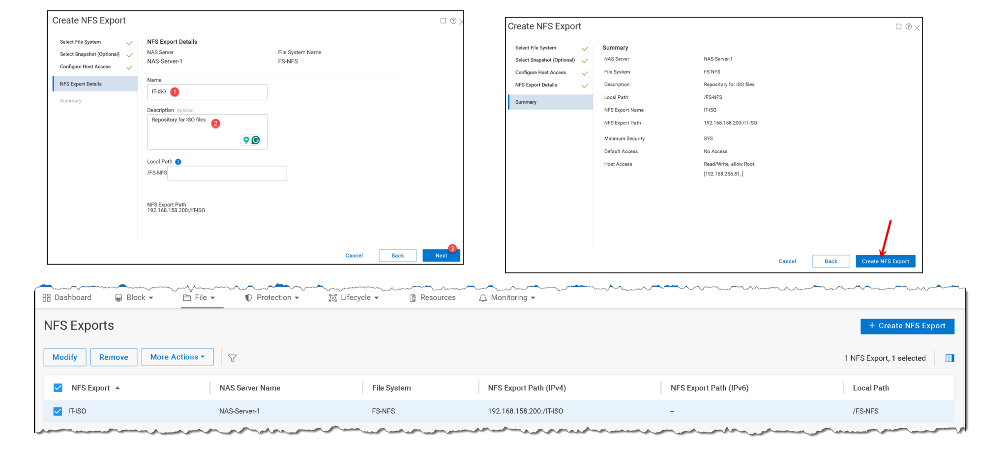
To mount the NFS share, access the client computer and mount it using the following command:
mount -t nfs 192.168.158.200:/IT-ISO /mnt/it-iso/


During the NFS Export creation, we defined only the host with IP address 192.168.255.81 with permission to mount the directory. If we try to mount from another host, we will have an error, as we can see in the following picture:

That’s it 🙂