Balancing a Web Application with NSX ALB is an article that shows how to balance web access to a specific application using the NSX Advanced Load Balancer.
Our aim is to show how to configure the NSX ALB Controller and create the Virtual Service to balance all client connections to the Web Servers. In this example, we have three Web Servers (Nginx) and all connections will be balanced using the Round-Robin Load Balance algorithm.
We have written an article that explains the necessary steps to deploy the NSX Advanced Load Balancer Controller. You can access this article at the below link:
https://dpcvirtualtips.com/nsx-advanced-load-balancer-deployment-steps/
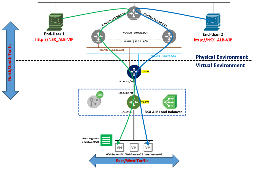
Logical Topology of Our Lab Environment
Here, we can see our basic lab topology. As we can see, we have three web servers backed on an NSX Segment and this Segment is attached to the Tier-1 gateway.
The Tier-1 gateway is connected to the Tier-0 gateway, and its have some uplinks with the physical network.
In this example, all end users are in the physical network, as we can see in the below picture. The NSX Load Balance needs a Tier-1 gateway to work properly. Because of that, we are showing the load balance icon next to the Tier-1 gateway just to remember this point:
What is the Purpose of using this Solution?
In this case, using a Load Balancer is an intelligent way to spread all connections to the backend services. We have a lot of Load Balancer algorithms to determine the way that these connections will be spread.
Furthermore, with a Load Balancer, we can add an extra layer to provide high availability for our application. In the topology above, for example, we have three web servers. Using a Load Balancer, we can provide this service by a unique IP address or a unique FQDN to the end user, and the responsibility to forward or redirect the end user’s traffic is to the Load Balancer service. If one backed web server fails or is unavailable on the network, the end-user does not necessarily need to know about that and your connections will be redirected automatically to another available web server inside the NSX ALB Pool.
In fact, in my view, this is a fantastic way to provide redundancy and high availability to access a specific application!
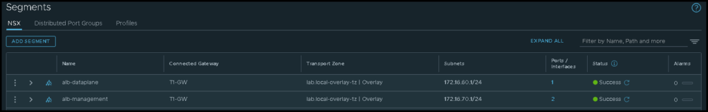
Creating the Required NSX Segments
Basically, the NSX ALB needs both NSX Segments:
- One Segment for the Management Traffic (alb-management)
- One Segment for the Dataplane Traffic (alb-dataplane)
Based on that, we need to create both segments before we start the next configurations. The below picture shows our NSX Segments:
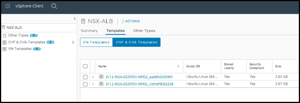
Creating the vSphere Content Library for the NSX ALB
Additionally, the NSX ALB requires a vSphere Content Library. A vSphere Content Library is necessary for the NSX ALB to store the files (OVA) to deploy the Service Engines (SE) on the computer cluster, for example. In our example, we created a Content Library called “NSX-ALB”:
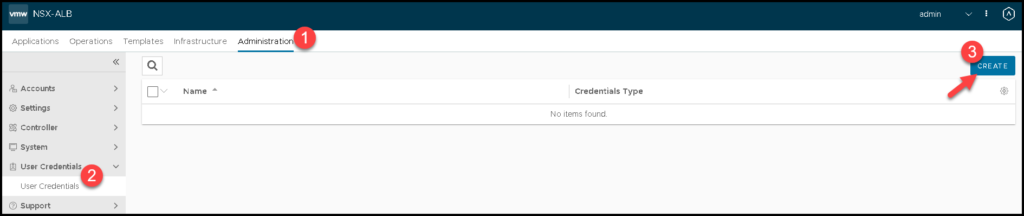
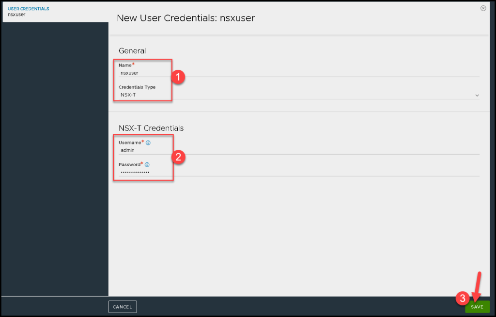
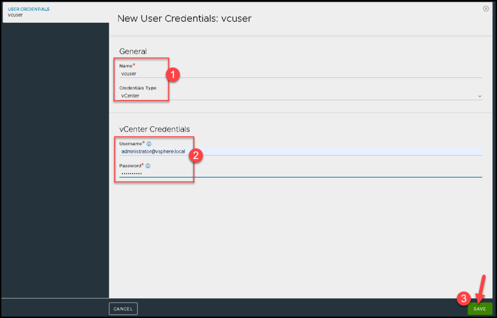
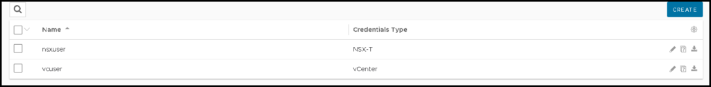
Creating the User Credentials
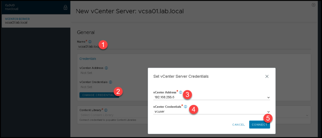
Now, we need to access the NSX ALB Controller GUI and create the user credentials. Here, we need to create the NSX Manager and the vCenter Server credentials. Both users will be used to integrate the NSX ALB with both solutions (NSX Manager and vCenter Server):
NSX Manager user – Here we need to type the admin credential used to access the NSX Manager. In this case, we are using the admin account:
vCenter Server user – Here we need to type the username used to access the vSphere Client. In this case, we are using the administrator@vsphere.local account:
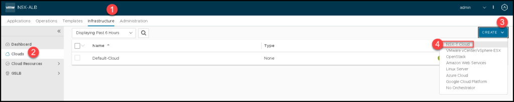
Creating a Cloud Connector
Before the NSX ALB Controller can create Service Engine VMs, you must create a cloud connector for the NSX environment.
The cloud connector defines the connectivity information for both the management and the data plane networks of the Service Engines, including:
- NSX Transport Zone
- NSX Segment
- Tier-1 gateway used as the default gateway
So, we need to access the menu:
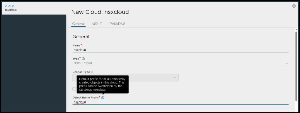
Infrastructure –> Clouds –> Create –> NSX-T Cloud
We need to type the name and type the object name prefix. All objects that will be created by the NSX ALB will have this prefix:
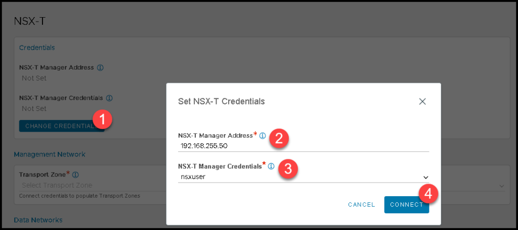
Next, under NSX-T, we need to specify the NSX Manager IP and the credential that will be used to connect to the NSX Management Cluster.
In this example, the IP address 192.168.255.50 is the VIP address of the NSX Management Cluster. The NSX-T Manager Credentials is the credential we created before:
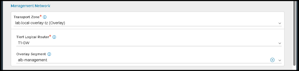
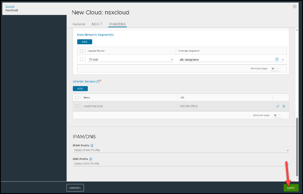
Under Management Network, we need to specify the Transport Zone, the Tier-1 gateway, and the NSX overlay segment used for the Management Network.
As I said before, in our example, I already created the NSX Segment “alb-management” for this purpose:
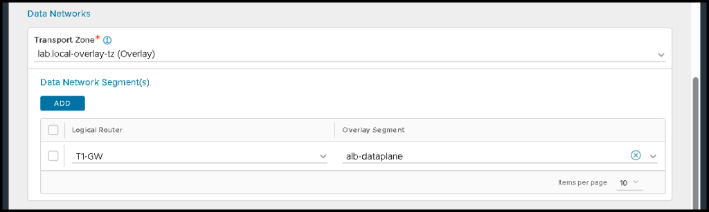
Under Data networks, we need to specify the Tier-1 gateway and the NSX overlay segment that will be used for the data plane. In this example, this segment is called “alb-dataplane”:
Under vCenter Server, we need to specify the vCenter Server details:
Specify the Content Library that will be used:
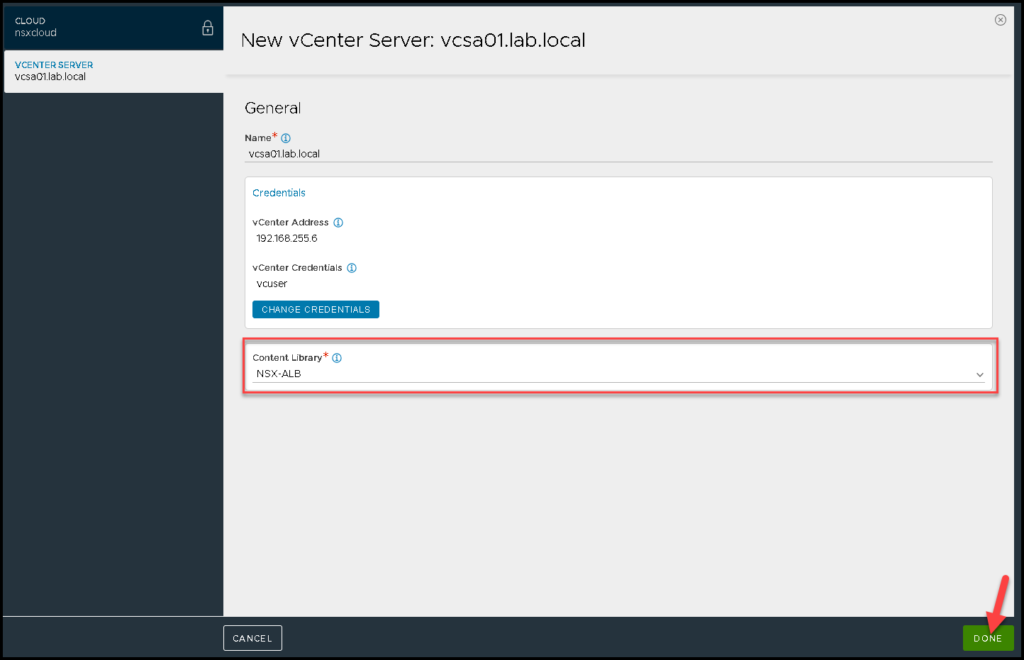
Under IPAM/DNS, in this case, we do not change or put anything. Click on SAVE:
The yellow bubble shows that the configuration is being placed. We need to wait some seconds:
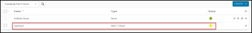
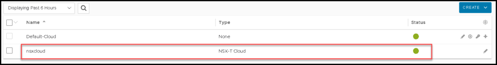
There we go 🙂
Here our NSX cloud connector is ready:
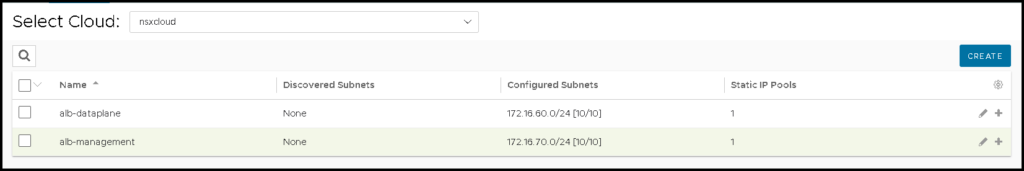
Specifying the Networks Inside Our NSX Cloud Connector
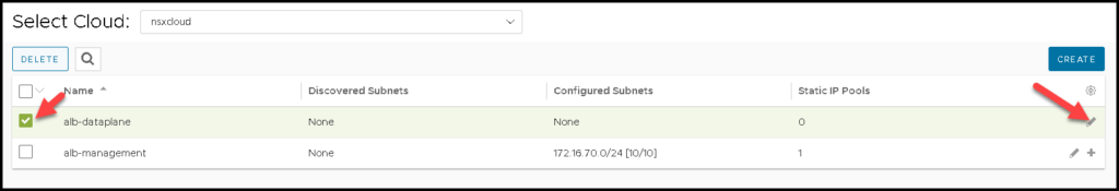
After creating the NSX Cloud Connector, we need to specify manually the network details of each NSX Segment. To do that, click on:
Infrastructure –> Cloud Resources –> Networks –> Under Select Cloud, choose the cloud connector that we created before
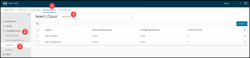
If your configuration is correct, you can see both NSX Segments.
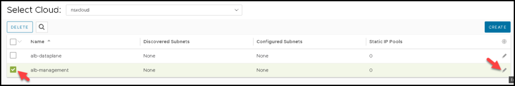
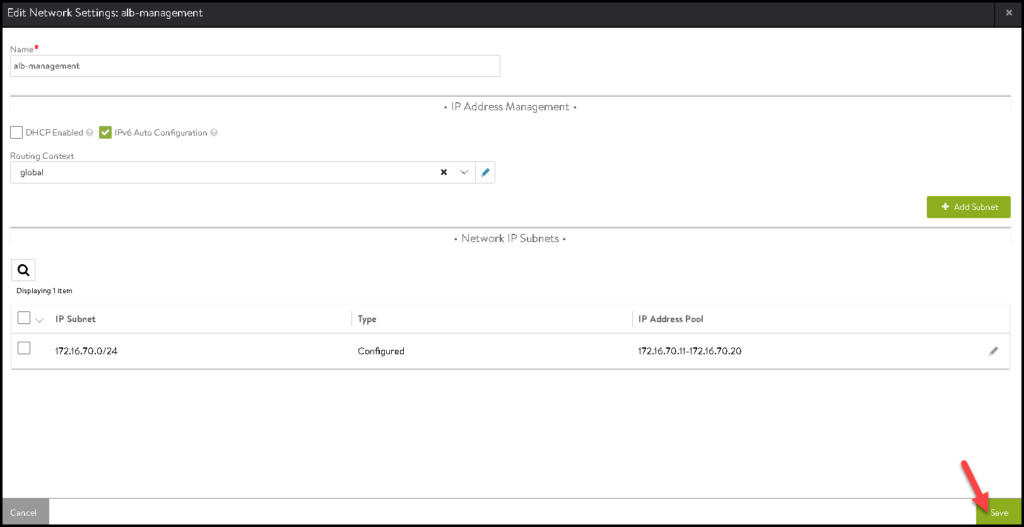
Select the management segment and click on the pencil icon:
Define the IP Subnet and the Static IP range that will be used for VIPs and SEs. Click on SAVE:
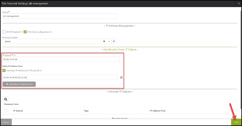
Click on SAVE again to save and follow to the next configuration:
Next, select the data plane segment and click on the pencil icon:
Here, we need to specify the IP Subnet and the Static IP range that will be used by the VIPs and SEs. Click on SAVE:
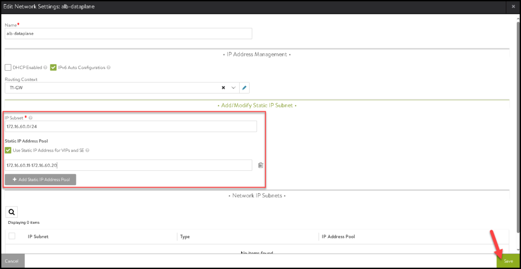
Click on SAVE again to save and follow to the next configuration:
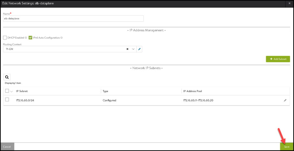
There we go 🙂
Both networks are configured:
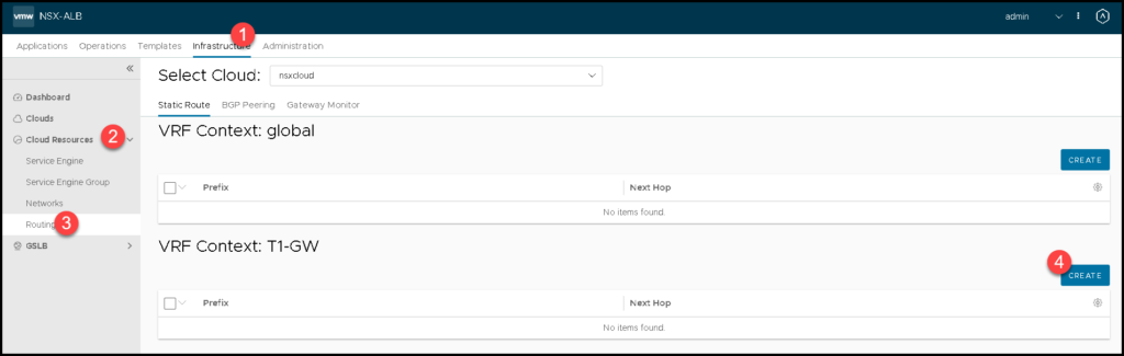
Creating the Default Route for the Tier-1 Gateway
As part of the configuration, we need to create manually a default route that will be used for the NSX ALB components placed on the NSX Data Plane Segment.
To do that, we need to access the menu:
Infrastructure –> Cloud Resources –> Routing –> Under Tier-1 VRF Context, click on CREATE
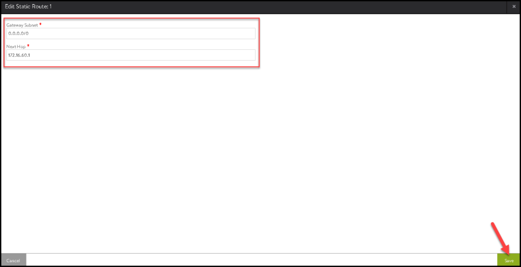
Type the subnet as “0.0.0.0/0” and the Next Hop as 172.16.60.1.
In our example, the IP address 172.16.60.1 is the IP used by the NSX overlay segment “alb-dataplane”. Click on SAVE:
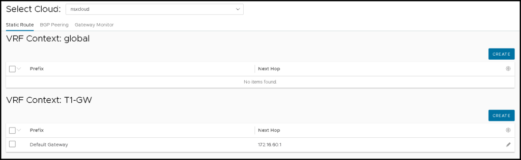
After that, we can see the route here:
Creating an NSX ALB Pool
So, an NSX ALB Pool basically is a configuration where we will specify all resources that will be available, or in other words, the resources that will be accessed by the end-user through the Load Balancer.
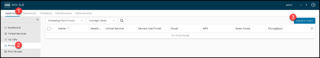
To do that, we need to access the menu:
Application –> Pools –> CREATE POOL
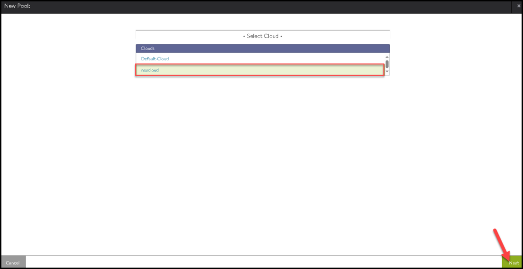
Select the Cloud Connector that we created before and click on NEXT:
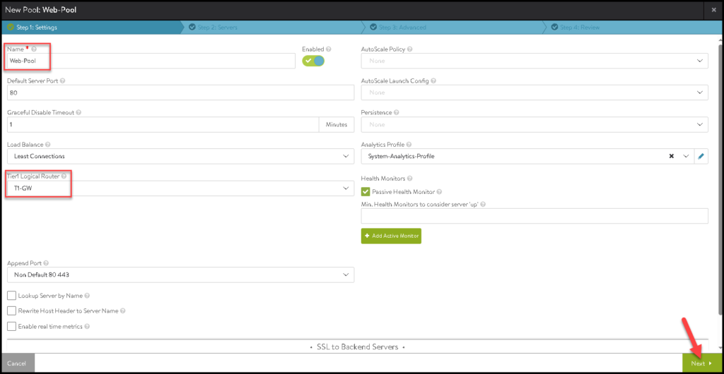
Type the Pool Name, Select the Tier-1 gateway and click on NEXT:
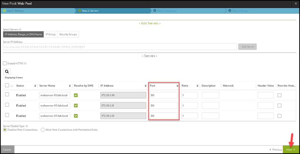
Under Servers, we need to type our servers that will be part of this pool.
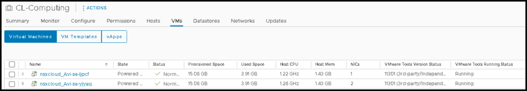
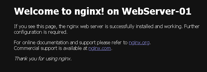
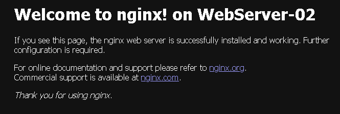
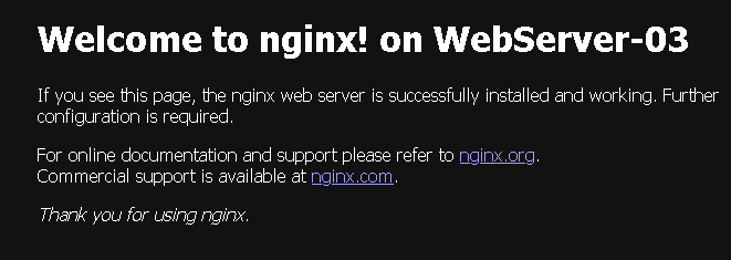
In our example, we are using three Web Servers, as we can see in the below pictures:
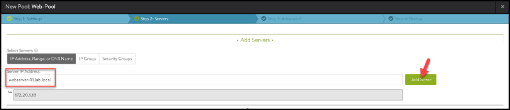
After adding all servers, adjust the Port as necessary. In our case, we are using three Web Server listening connections on the TCP port 80. Click on NEXT:
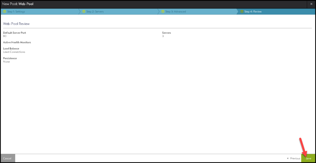
Click on SAVE to finish:
Creating an NSX ALB Virtual Service
The Virtual Service is the configuration where we will specify the Virtual IP that we will use to access our resource placed on the NSX ALB Pool.
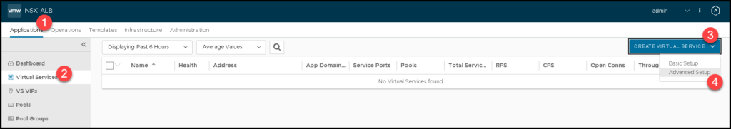
To create an NSX ALB Virtual Service, we need to access the menu:
Application –> Virtual Services –> CREATE VIRTUAL SERVICE –> Advanced Setup
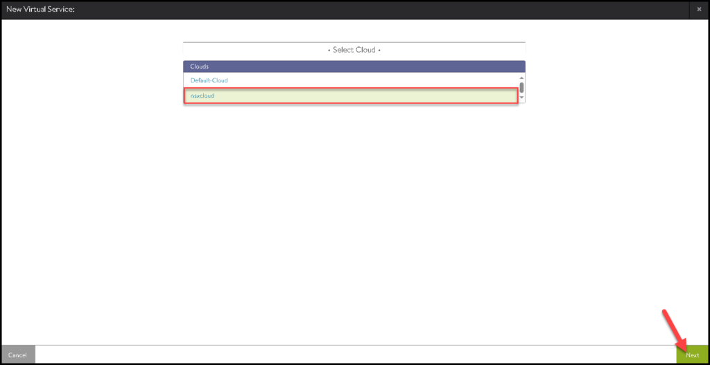
Select the Cloud Connector that we created before:
Type the Virtual Service Name, and the IP address of the FQDN for the VIP, select what Tier-1 gateway is using for that, and select the Pool that we previously created. Click on NEXT to continue:
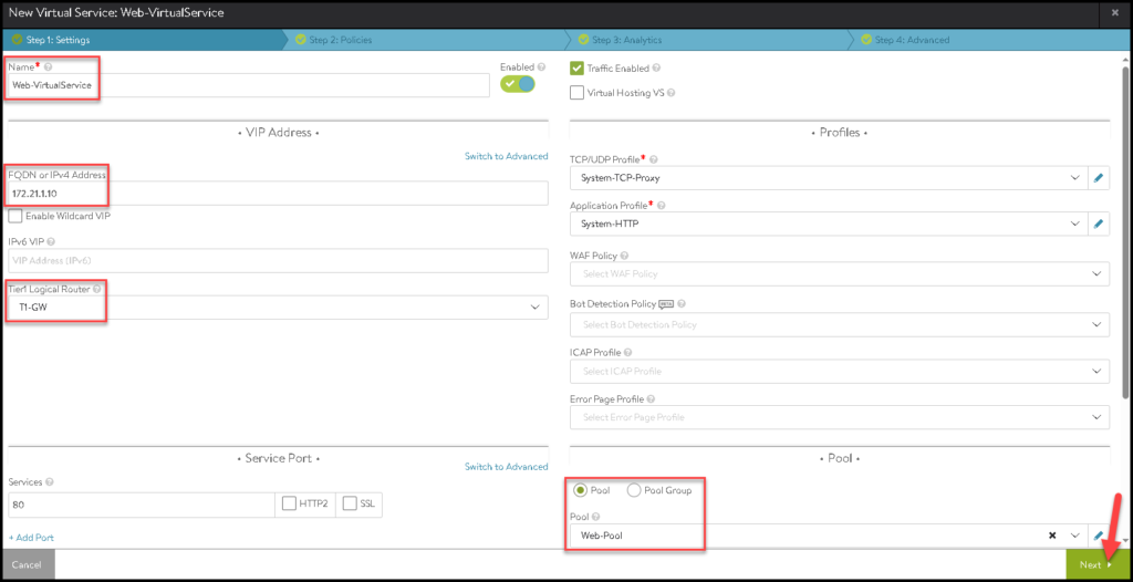
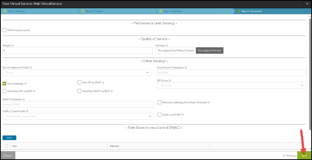
Click on SAVE to finish the creation wizard:
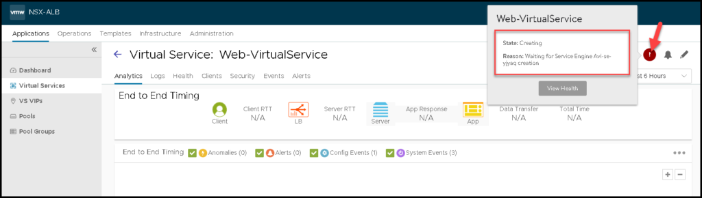
As we can see in the below picture, the Virtual Service is in creating status. We need to wait some minutes while this process is running:
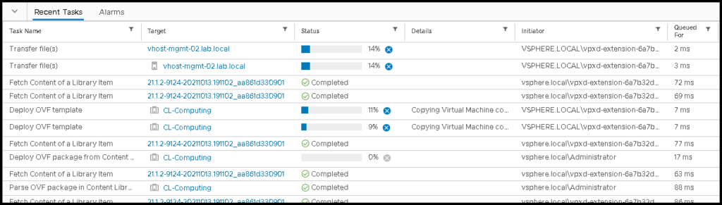
Under Recent Tasks on the vSphere Client, we can see that the Service Engines (SE) are being deployed on the Computing Cluster (next to the workload that we need to access):
After some minutes, we can see the Service Engines VMs:
And now, our Virtual Service is ready for use 🙂
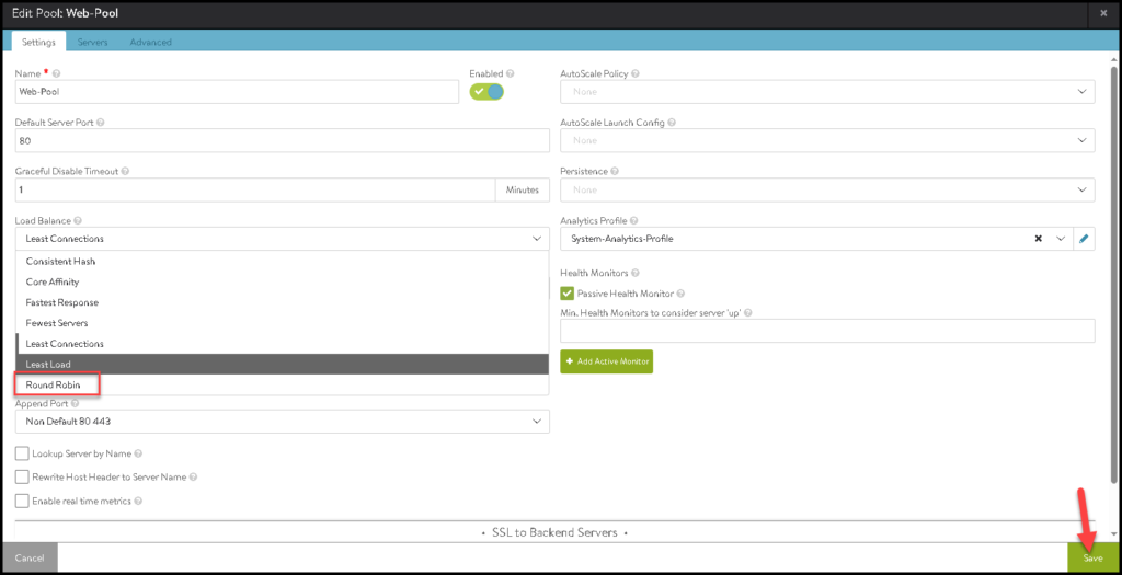
Tip: We can edit the NSX ALB Pool and change the Load Balance algorithm to Round Robin:
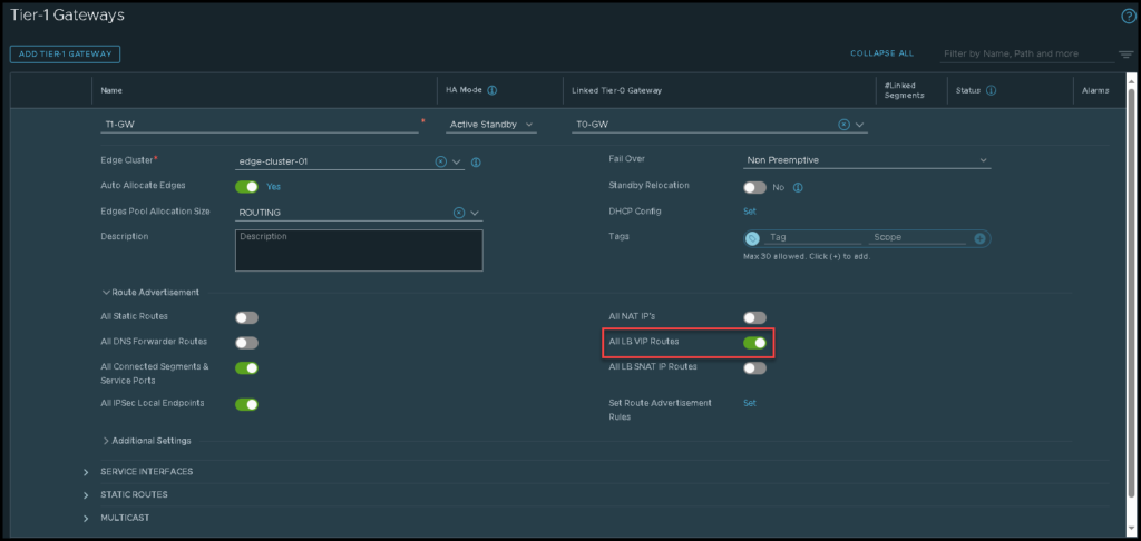
Tier-1 Gateway Route Advertisement
So, we need to edit the Tier-1 gateway and turn on the toggle under Route Advertisement just to advertise the LB VIP route to the Tier-0 gateway. The picture below shows how we can do that:
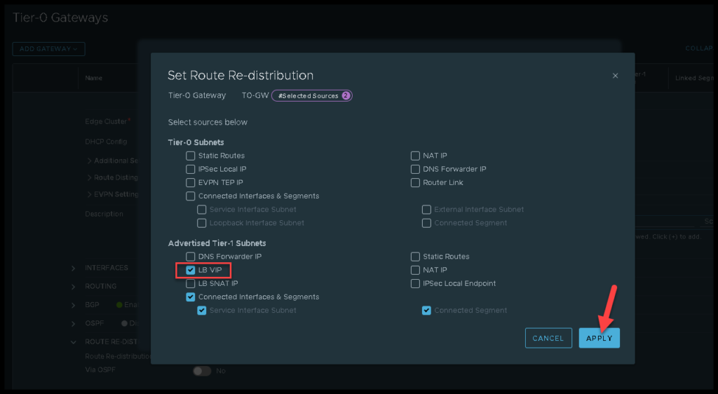
Tier-0 Gateway Route Re-Distribution
In the same way, on Tier-0, we need to redistribute the LB VP route learned from the Tier-1 gateway to the Tier-0 peers. We can see how to do that in the below picture:
Accessing the Web Application Balanced by the NSX ALB
From a computer outside the NSX environment (on a physical network, for example), we can access the Web Application using the NSX ALB VIP. In our example, the VIP address is:
http://172.21.1.10As we are using the Roud Robin as the Load Balance algorithm, each access will redirect to one Web Server 🙂 This is the expected behavior here:
In the short video, we can show in a practical way the process of accessing a web application through the NSX ALB Virtual IP. In this example, we already created a DNS entry for our Virtual IP:
http://webserver-vip.lab.localLook that we are accessing the FQDN for the Virtual IP and are simulating a lot of access to this Virtual IP. For each access, the NSX ALB balanced or redirected us to one different Web Server (Round Robin):
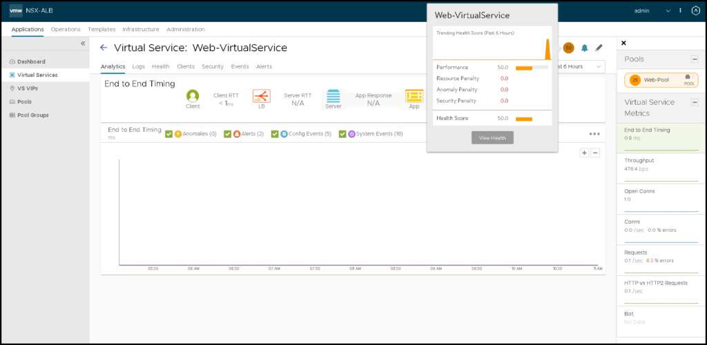
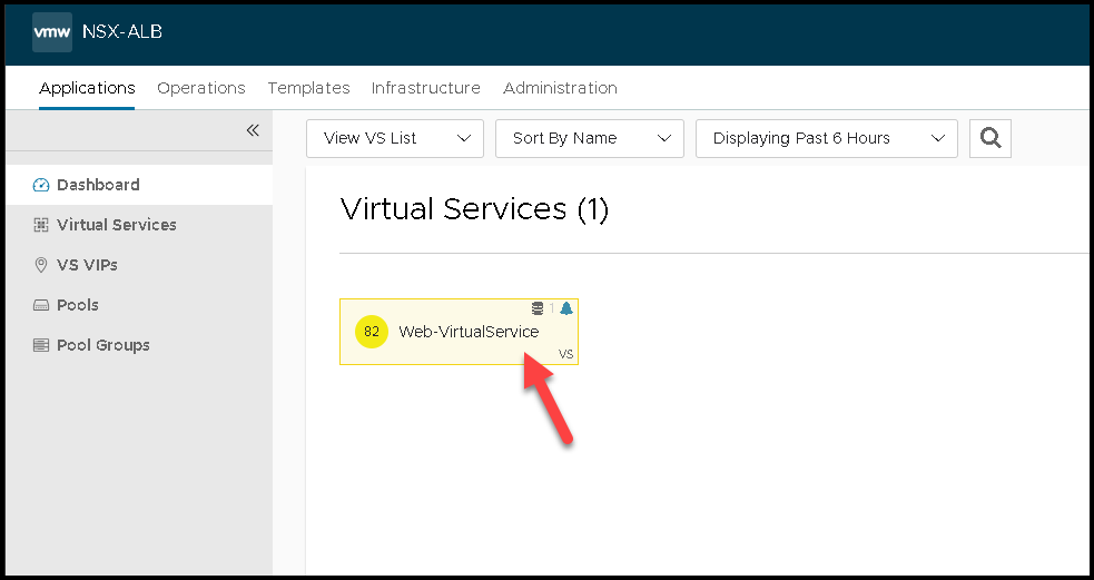
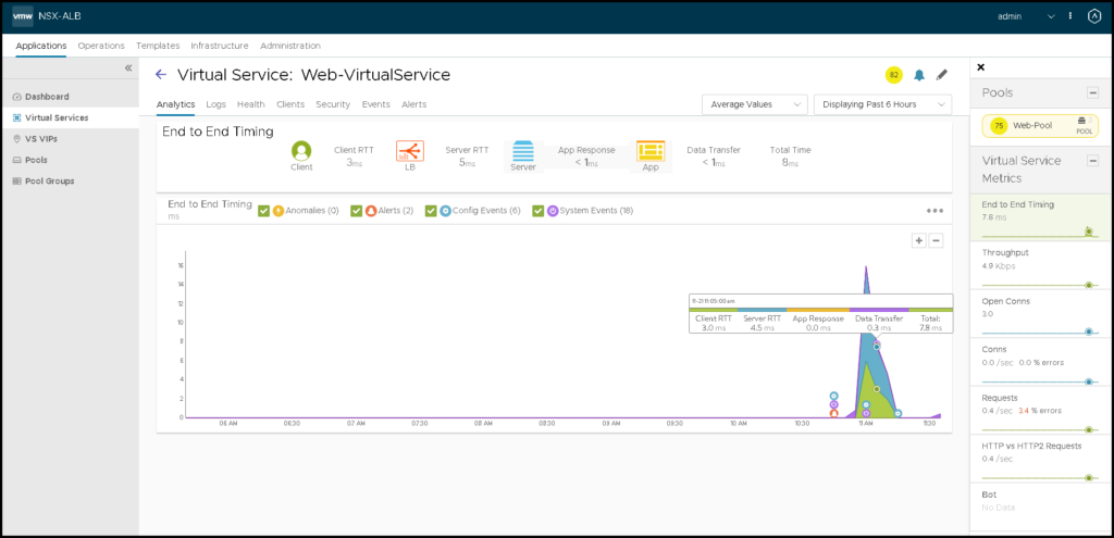
Checking Details of the Virtual Services
Under Applications –> Dashboard, we can see all available Virtual Services.
We can click on one to see more details about that:
That’s it for now 🙂