Explaining how inter SR iBGP works in the NSX is an article that provides an example of how the inter SR iBGP routing process works in advertising routes between Edge Transport Nodes in a Tier-0 Gateway.
I want to talk about some NSX articles that we wrote. These articles are about NSX Introduction, NSX Manager (How to Deploy an NSX Management Cluster), about micro-segmentation, about NSX ALB (Advanced Load Balancer), and so on. So, feel free to check each one by accessing the following link:
NSX Archives – DPC Virtual Tips
Warning: To explain how inter SR iBGP works in the NSX, we will use a picture from VMware by Broadcom. We use this picture only to show this example and for learning purposes!
First and foremost, What is BGP?
BGP is an acronym for Border Gateway Protocol. This is a dynamic routing protocol used to exchange routing information between neighbors (between devices that are capable of using the same protocol).
We have two types or two modes of using BGP:
- eBGP: eBGP is an acronym for External BGP. It is used between autonomous systems. It is used and implemented at the edge or border router that provides interconnectivity for two or more autonomous systems. It functions as the protocol responsible for the interconnection of networks from different organizations (different autonomous systems) or the Internet.
- iBGP: iBGP is an acronym for Internal BGP. It is used inside the autonomous systems. It is used to provide information to your internal routers. It requires all the devices in the same autonomous systems to form a full mesh topology.
In the NSX context, we use eBGP to exchange route information between Tier-0 gateway with the upstream routers (Physical L3 devices) and we use iBGP to exchange route information between edge transport nodes (inside the same edge cluster, for instance).
What is the Challenge Here?
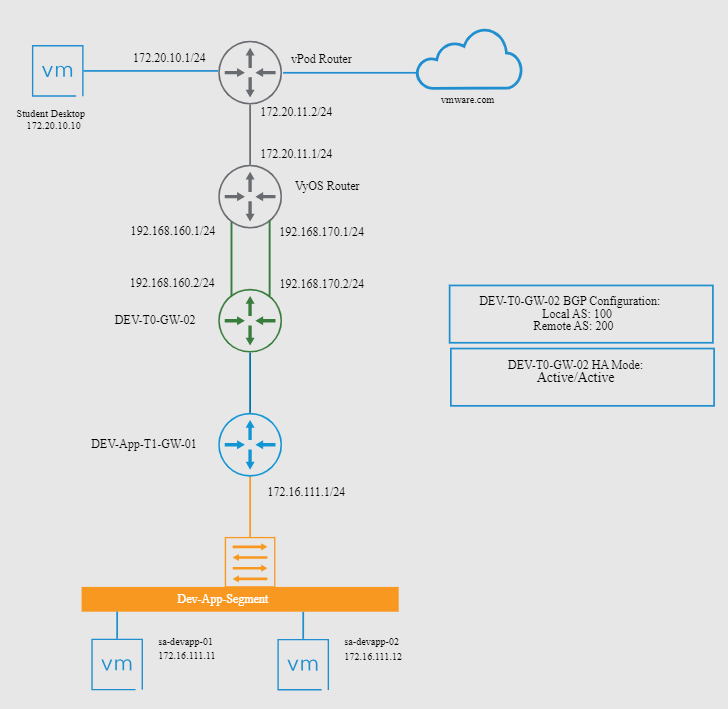
Both VMs on the back-end segment “Dev-App-Segment” can reach the “Student Desktop (172.20.10.10)”.
However, the VM “sa-devapp-02” cannot reach the external website “vmware.com”.
As we can see, the Tier-0 gateway “DEV-TO-GW-02” has both connections to the upstream router “VyOS Router”. They are using BGP to exchange routers between each one.
The Tier-0 gateway is in HA mode “Active-Active”. So, our challenge here is just to analyze each SR (Service Router) routing table and enable the inter-SR iBGP for them to exchange routes between each one:
Checking What are the Edge Transport Nodes used by the Tier-0 Gateway
A simple way to check it is by accessing the NSX Manager UI and under the Tier-0 gateway configurations, checking the interface details.
In this case, for instance, the Tier-0 gateway has two interfaces used by connecting it to the upstream router:
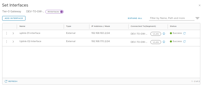
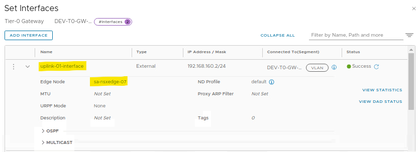
Expanding each interface configuration, it is possible to see what edge node the uplink is using:
uplink1 is using the sa-nsxedge-07:
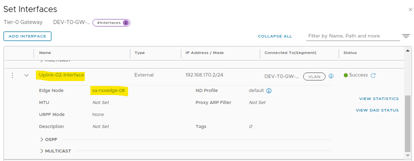
uplink2 is using the sa-nsxedge-08:
Checking the Routing Table on Each Service Router
As we told you before, the Tier-0 gateway is configured in HA Active-Active. So, each edge transport node is hosting a Service Router instance. Based on this fact, we need to access each VRF SR instance and get the routing table:
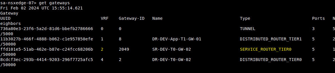
1- Access the edge transport node “sa-nsxedge-07” by SSH and check the gateways it has.
Looks the SERVICE_ROUTER_TIER0. This is our Service Router instance for the Tier-0 gateway. Each gateway has its own VRF number. In this case, for instance, the VRF is 2 for the Tier-0 gateway Service Router:
2- Access the VRF 2:
vrf 23- Get the routing table:
get route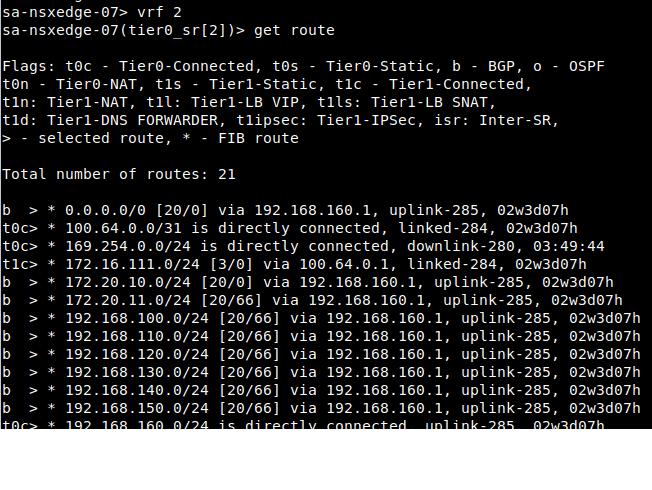
4- We need to do the same process for the other edge transport node (sa-nsxedge-08):
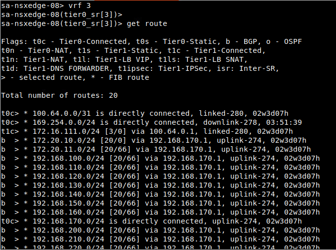
Note: Look that the “Total number of routes” for each one is different (one has 21 routers and the other has 20 routes). It probably means that the upstream router is advertising the default route (0.0.0.0/0) only through the uplink to the edge transport node 07 (sa-nsxedge-07).
Based on this, all traffic that needs to reach out to the virtual environment (the physical environment or Internet, for instance) through the edge transport node 07 will not have success (because it does not have a default router).
How can we fix it? We will see it on the next topic 🙂
Enabling the Inter-SR iBGP
Based on the fact that the Tier-0 gateway is in Active-Active HA mode, enabling the Inter-SR iBGP on the Tier-0 gateway will create an internal connection between both edge transport nodes just to share routing information.
The expected behavior here is, after enabling the iBGP, the default route (0.0.0.0/0) learned by the first edge transport node (sa-nsxedge-07) will be advertised to the other edge transport node (sa-nsxedge-08) through the iBGP protocol. Let’s get started:
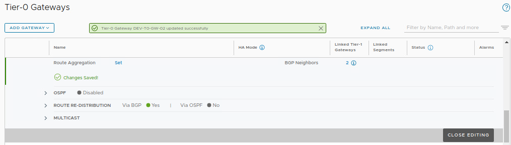
1- Edit the Tier-0 gateway configuration and, under BGP, enable the Inter-SR iBGP:
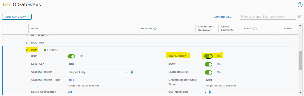
2- Save the changes:
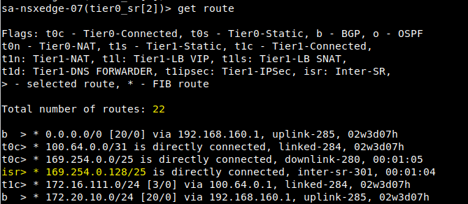
3- On each edge transport node, check the routing table again:
In the first edge transport node, we have a new “isr” route (isr = Inter-SR):
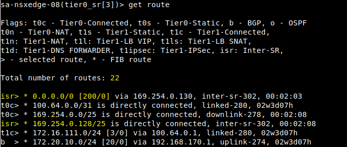
In the other edge transport node, we have the same route that we saw before and we have a default route, learned by the first edge transport node 🙂
It means that all traffic to the Internet or external networks through this edge transport node 08 (sa-nsxedge-08), will be sent to the edge transport node 07 (sa-nsxedge-07), and then sent to the upstream router:
To Wrapping This Up
We could see how important it is for the iBGP configuration to exchange routing information between Service Routers, especially when using the Active-Active HA mode in the Tier-0 configuration.