Some Examples of NSX Topologies show some topologies that can be used in the NSX environment.
Firstly, I would like to share some documents related to the NSX Design Guide. You can check more details on these links if you prefer:
https://nsx.techzone.vmware.com/resource/nsx-reference-design-guide
https://www.vmware.com/content/dam/digitalmarketing/vmware/en/pdf/products/nsx/vmw-nsx-network-virtualization-design-guide.pdf
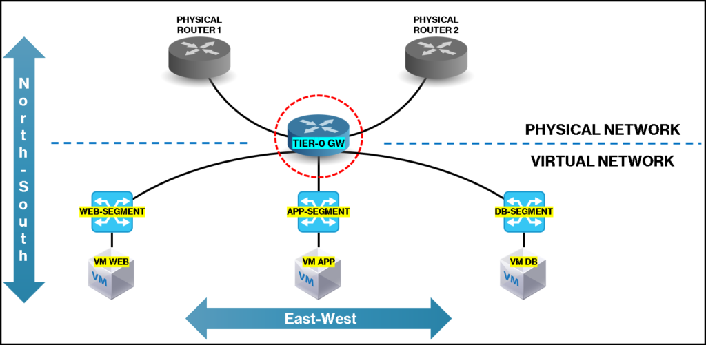
Single-Tier Topology/Deployment
On this topology, we only have the Tier-0 gateway.
All NSX Segments (Virtual Switches) are connected directly to the Tier-0 gateway.
As we can see in the below picture, the Tier-0 gateway is responsible for connecting the virtual network (inside the NSX) to the physical network (outside the NSX). Furthermore, all Segments are connected to the Tier-0 gateway:
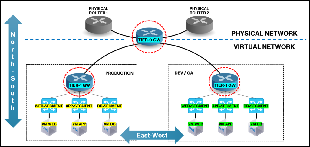
Multi-Tier Topology/Deployment
On this topology, we have the Tier-0 gateway and one or multiple Tier-1 gateways.
All NSX Segments (Virtual Switches) are connected to the Tier-1 gateway, and they are connected to the Tier-0 gateway.
As we can see in the below picture, we have both Tier-0 and Tier-1 gateways. The Tier-0 gateway is responsible for connecting the virtual network (inside the NSX) to the physical network (outside the NSX) and all Segments are connected to the Tier-1.
The connection between the Tier-0 and Tier-1 gateway is automatically created when we connect the Tier-1 to the Tier-0 gateway – This interface/connection is called “RouterLink Interface”:
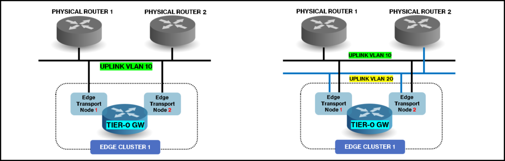
Tier-0 Gateway Uplinks
As we can see above on each topology, the Tier-0 gateway is responsible for connecting the “virtual world” to the “physical world”. Each Tier-0 gateway can have one or multiple uplinks to the physical router/device.
It’s a good idea (for high availability purposes) to have more than one uplink. In the below picture, we have an example of some possibilities that we have: (here is just an example -you can use more than 2 uplinks if your environment needs it):
Gateway Interfaces
In the below picture, we have all the interface names that we have in the NSX infrastructure:
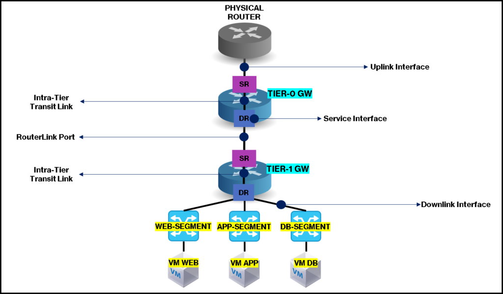
Uplink Interface: Connection to the physical network;
Downlink Interface: Connection to the “workloads” (VMs, for example);
RouterLink Port: Connection between the Tier-0 and Tier-1 gateways. This interface/connection is created automatically when both gateways are connected – the subnet 100.64.0.0/10 is used for this transit network);
Intra-Tier Transit Link: Connection between SR and DR components. This interface/connection is automatically created when the SR component is created. The subnet 169.254.0.0/28 is used for this transit network;
Service Interface: Special interface where we can use for “VLAN-Based” traffic. This interface works such as a “Downlink Interface”.
Gateway Components
Each gateway (Tier-0 or Tier-1) has two components called SR (Service Router) and DR (Distributed Router).
DR – Distributed Router:
- Responsible for the distributed routing of all east-west network traffic;
- Responsible for the packet-forwarding;
- It is distributed on all Transport Node Devices (Host and Edge Transport Nodes);
- It has an active local gateway on all Host Transport Nodes. It allows the routing to be performed locally on the Host Transport Node.
SR – Service Router:
- Responsible for routing the north-south traffic – “BGP peering”;
- This service is created when uplinks between the Tier-0 gateway and the Physical Router is established;
- Can perform static and dynamic routing;
- Can execute centralized services such as NAT, Load Balancing, Gateway Firewalling, VPN, etc;
- Only is created if the Edge Transport Node is part of an Edge Cluster.
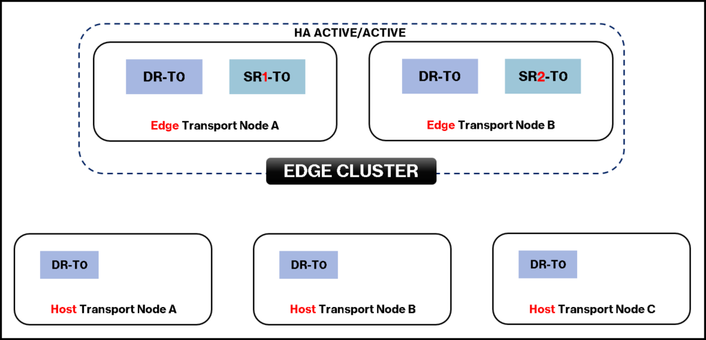
Gateway Components – Physical View
In the below picture, we can see a physical view of each Transport Node Device (Host and Edge Transport Node) and where we can find the SR and DR.
Just to remember, the DR component is distributed on all Transport Node Devices (Host and Edge Transport Nodes), while the SR component only resides on the Edge Transport Node Devices:
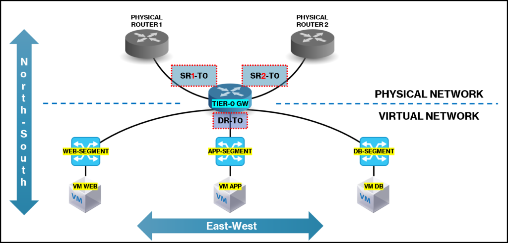
Gateway Components – Logical View
In the below picture, we can see the logical view:
This article is a small piece of this deeply subject. But, the aim here is just to introduce it and give the reader a little knowledge about that 🙂