

This guide walks through deploying a new Dell PowerFlex 4.5.2 software cluster with PowerFlex Manager. The lab uses a CSV installation topology to define a two-layer design and a five-node MDM cluster, then verifies the deployed resources in the management interface.
This is a nested lab for learning and demonstration. It is not a production deployment design.
If you are new to PowerFlex, start with Getting Started with Dell PowerFlex: Architecture and Key Components. For a walkthrough of an earlier PowerFlex 3.6.4 nested lab, see A Hands-On Journey Through Dell PowerFlex Cluster Deployment. The older article uses a different release and deployment workflow, so do not reuse its package or operating-system assumptions for this 4.5.2 deployment.
PowerFlex Lab Topology
This lab uses PowerFlex 4.5.2 with PowerFlex Manager 4.6.x. Dell’s software deployment guide covers PowerFlex 4.5.2 and later with PowerFlex Manager 4.6.x. The procedures in this article are for a software-only deployment; PowerFlex Rack and PowerFlex Appliance have their own installation documentation.
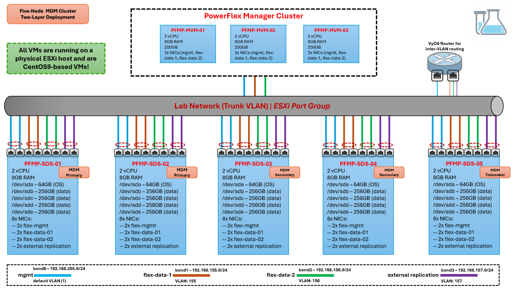
The physical host runs VMware ESXi. The PowerFlex nodes are virtual machines connected to a shared port group on a vSphere Standard Switch. Because this is a nested environment, the virtual nodes share the physical host, network, and storage failure domains. The setup is useful for learning the workflow, but it does not reproduce production performance or availability.
The lab uses a two-layer architecture, separating compute from storage. The five-node MDM cluster is deployed with the storage nodes. SDS components contribute storage devices, while SDC components on compute nodes provide hosts with access to PowerFlex volumes. The exact component placement must match the uploaded CSV and the design supported for the selected release.
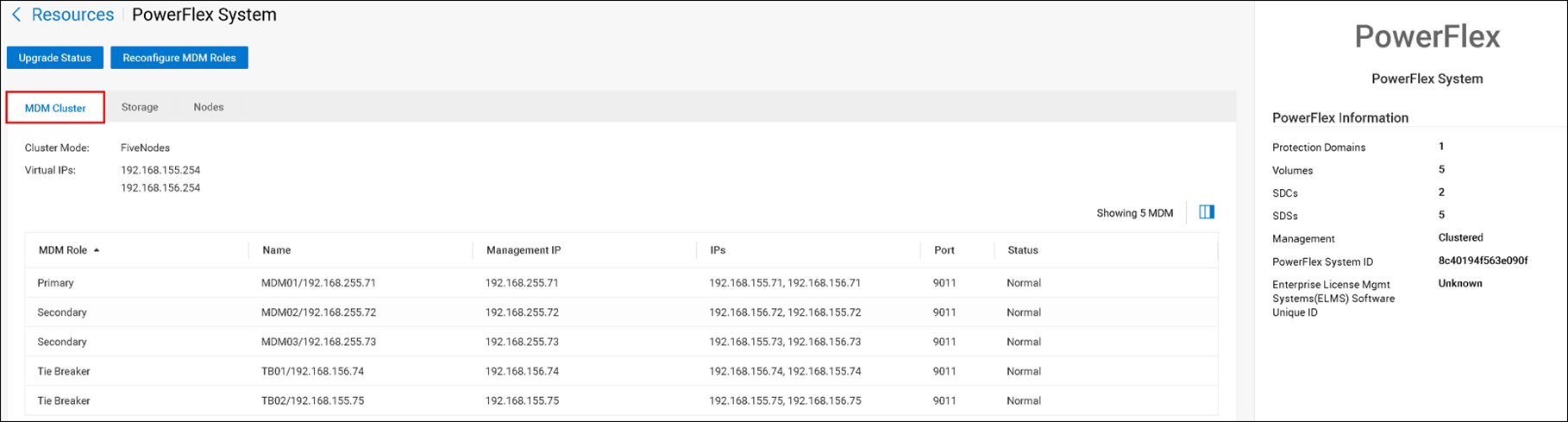
The five MDM nodes have distinct cluster roles: one primary, two secondary managers, and two tiebreakers. Two data networks, Flex Data 1 and Flex Data 2, provide the network paths defined in the CSV. A separate management network is used for administrative access.
Important: MDM virtual IPs are used by SDCs and other components to communicate with the active MDM. They are not the path over which application volume data flows. Volume I/O travels between SDCs and SDSs over the configured data path. Make sure the CSV assigns the correct IP roles to each network.
A VyOS virtual router provides routing between the isolated lab networks. For configuration steps, use the official VyOS documentation for the version you have installed:
Prerequisites
Before starting the deployment, confirm that PowerFlex Manager is deployed and healthy, that its FQDN resolves from the lab, and that you can sign in with an account authorized to deploy a cluster. For the version pairing used here, use PowerFlex Manager 4.6.x with PowerFlex 4.5.2.
Prepare the following items:
- PowerFlex 4.5.2 installation artifacts that match the operating systems used by the nodes.
- A validated CSV topology file containing the node names, component roles, network assignments, MDM virtual IPs, and storage-device mappings.
- Static IP addresses and DNS records for management and data networks.
- The required routing between management, data, and client networks.
- Clean storage devices for the initial deployment, or a deliberate plan for handling data on previously used devices.
For the management-platform operating mode and version requirements, use Dell’s PowerFlex 4.5.x installation documentation. If the blog article is published under another URL, add its verified internal link here.
Deploy the Cluster from a CSV Installation File
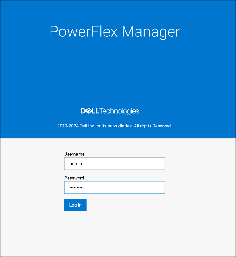
First, access the PowerFlex Manager UI using the cluster FQDN or IP. For this lab, the FQDN of the PowerFlex Cluster is:
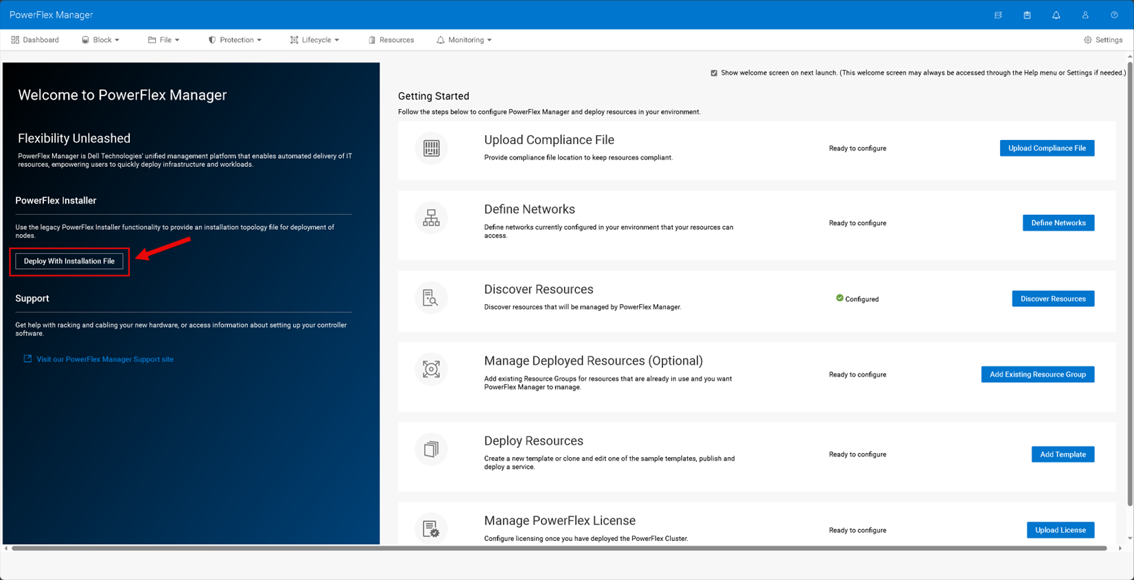
On the “Getting Started Page,” click “Deploy With Installation File”:
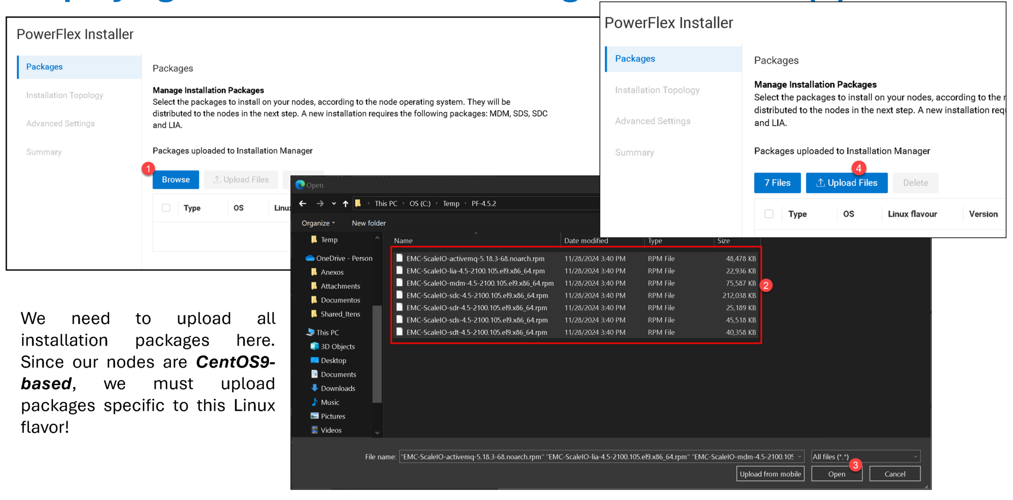
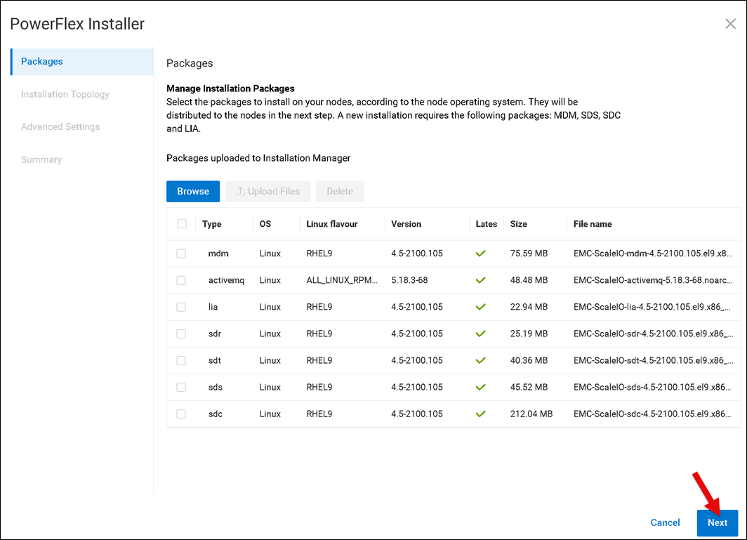
After uploading all packages, click on NEXT to continue:
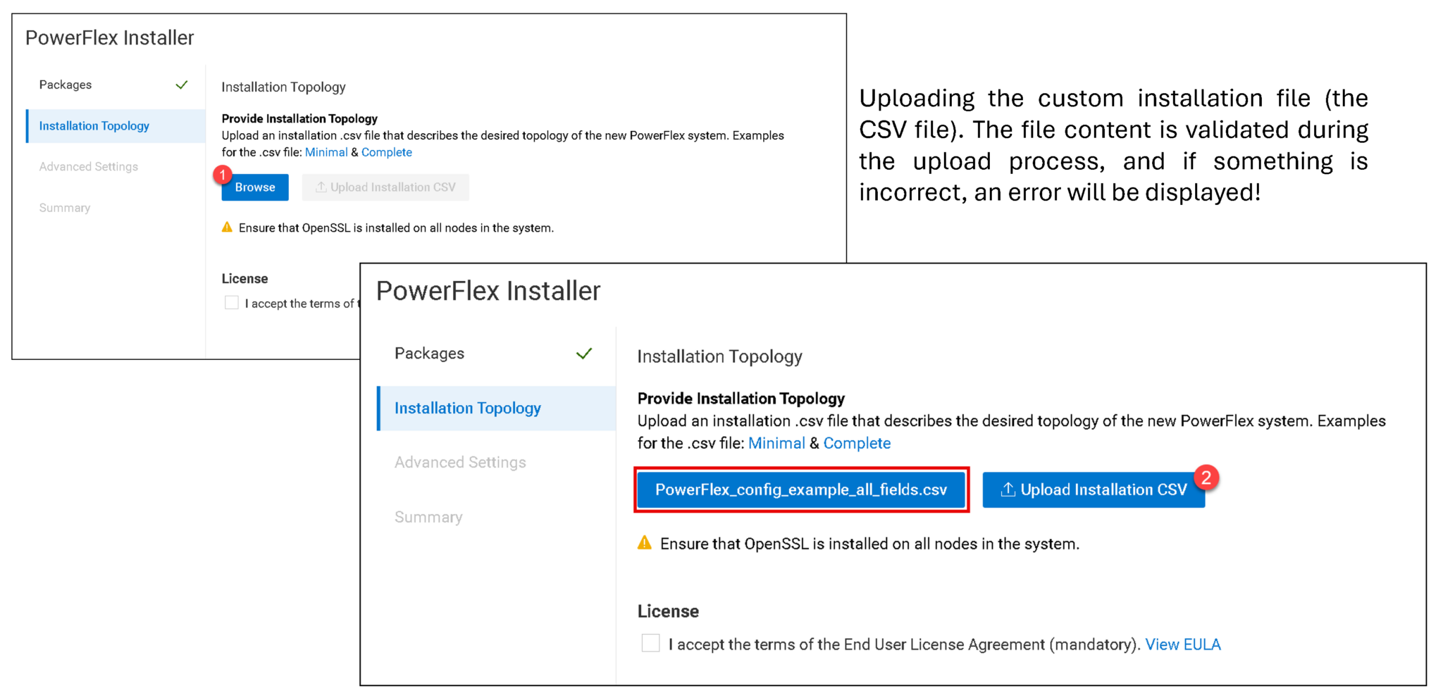
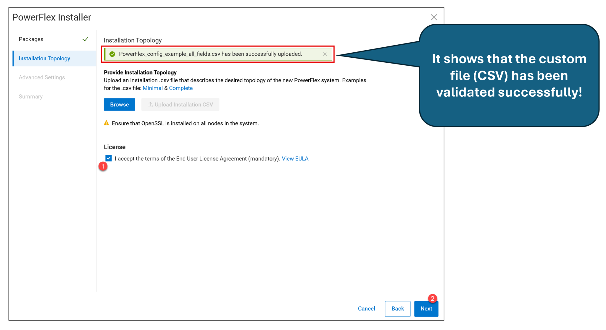
I want to share a copy of my custom file (CSV). You can download it using the following link:
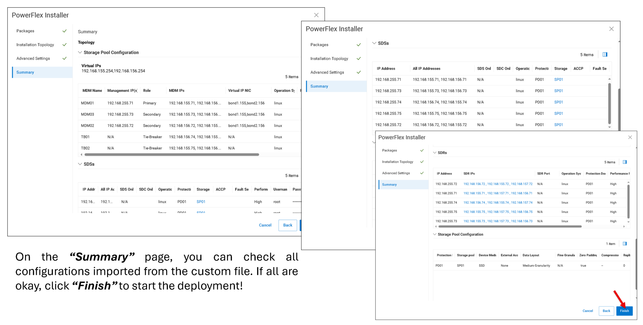
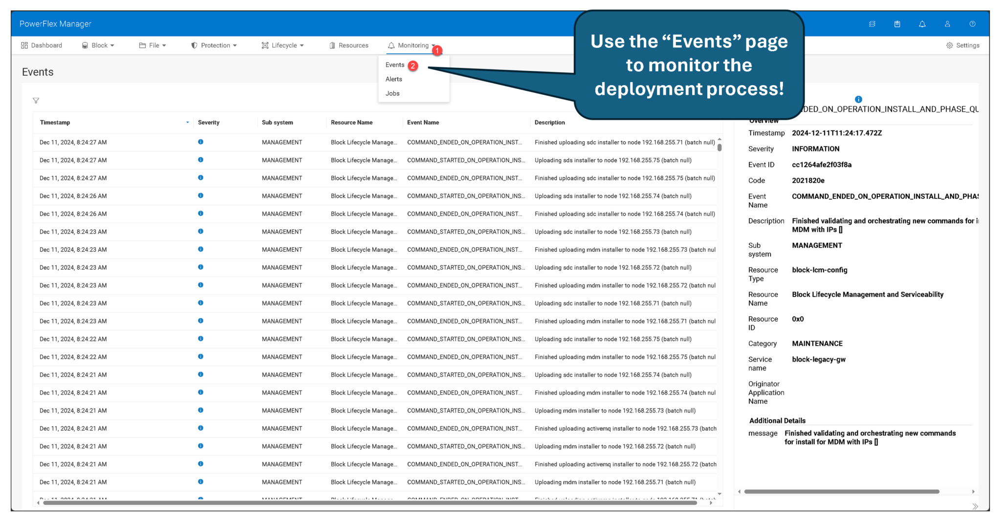
Verify the New PowerFlex Cluster
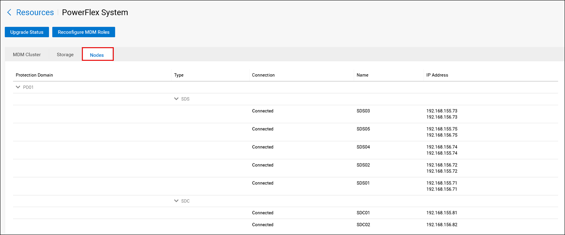
After deployment completes, open the Resources page and confirm that the expected nodes and MDM cluster are present. For a five-node MDM cluster, verify the expected primary, secondary, and tiebreaker roles and confirm that the cluster reports a healthy state.
The lab uses two MDM virtual IPs, one on each configured data network. Confirm that both are present and assigned to the intended interfaces. These addresses provide a stable way for SDCs to reach the active MDM; they do not replace the SDS data path used for volume I/O:
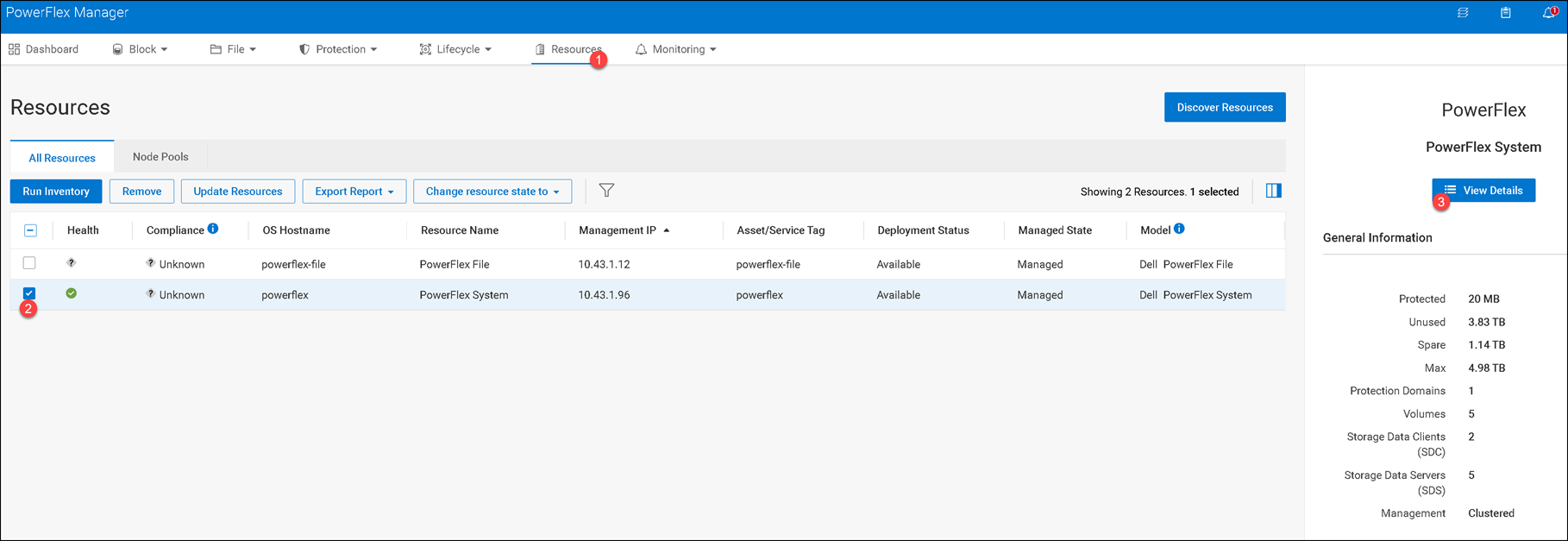
Use the Summary panel to review the cluster overview, including the number of Protection Domains, Volumes, SDCs, SDSs, and the System ID. For a newly deployed system, it is normal for the volume count to be zero until you create volumes.
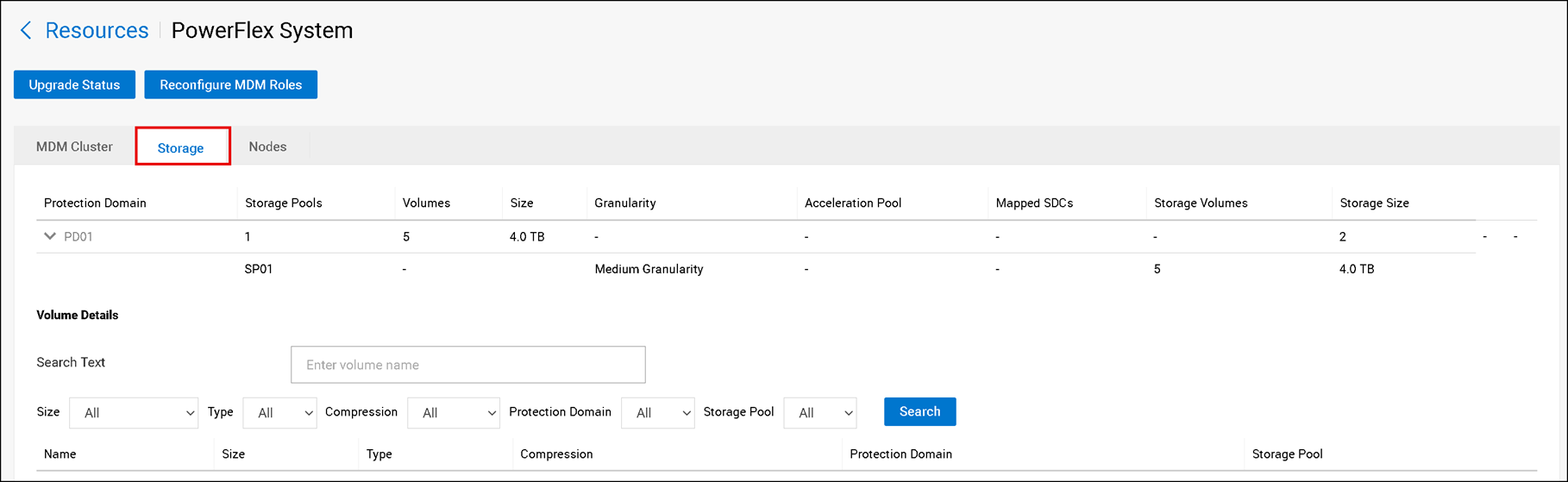
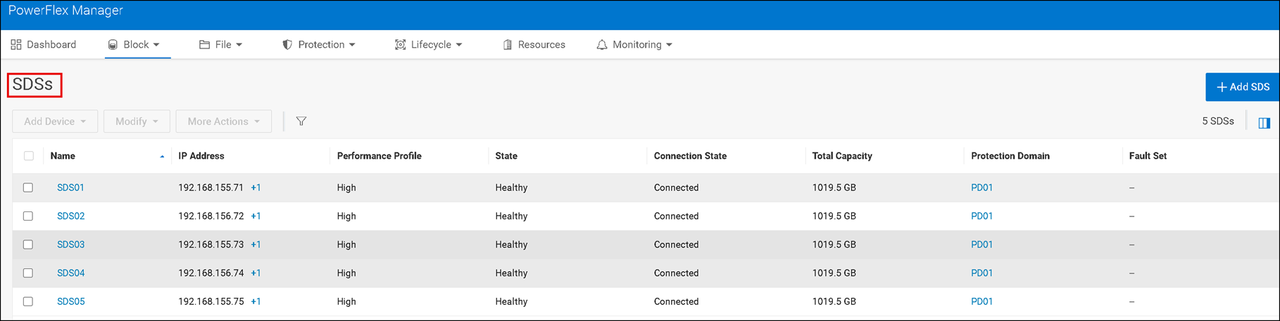
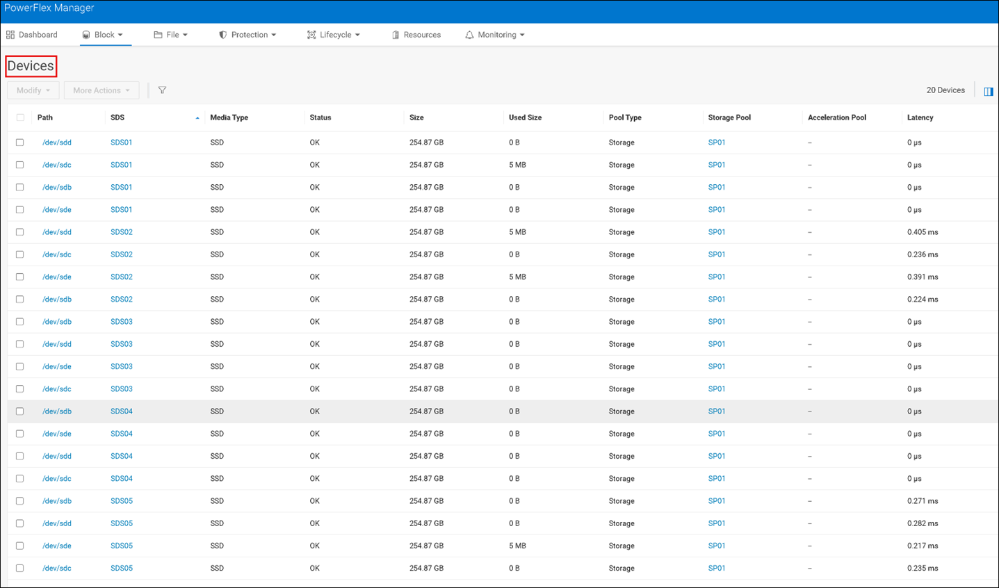
Review the Storage and Nodes tabs, then inspect the Block menu. Check the Protection Domains, Storage Pools, SDSs, Hosts, and Devices. Confirm that the expected storage devices were added to the correct SDSs and that no unintended disk was selected for overwrite:



Closing Thoughts
Deploying PowerFlex 4.5.2 from a CSV makes the intended cluster topology explicit and repeatable, but a successful upload alone does not prove that the design is sound.
Validate the supported software and operating-system combination, review every network and device assignment, and confirm that the five-node MDM cluster and its data paths are healthy after deployment.
With those checks complete, this nested lab provides a safe place to explore PowerFlex Manager and the cluster’s storage resources; production deployments should follow Dell’s release-specific support matrix and validated architecture guidance.
External References
- Dell — PowerFlex 4.5.2 and PowerFlex Manager 4.6.x Install and Upgrade Guide Defines the release scope for deploying PowerFlex 4.5.2 and later with PowerFlex Manager 4.6.x, and distinguishes software-only procedures from Rack and Appliance documentation.
- Dell — Deploy a PowerFlex Cluster Using a CSV Topology File Official PowerFlex Manager workflow for uploading installation artifacts and a CSV topology, accepting the EULA, reviewing advanced settings, and monitoring the deployment.
- Dell — Prepare the CSV Topology File Guidance for building the installation topology file and understanding the fields used to describe PowerFlex nodes, networks, components, and storage.
- Dell — PowerFlex Operating-System Support Matrix Maps supported operating-system releases to PowerFlex versions and components. Consult the current matrix before selecting Linux distributions for a deployment.
- Dell — PowerFlex 4.5.x Networking Explains PowerFlex network roles and the distinction between management/control communication, SDS-to-SDS operations, and the SDS-to-SDC data path.
- Dell — MDM Cluster Virtual IP Addresses Describes how MDM virtual IPs provide stable addresses for SDCs and other system components to reach the active MDM.
- Dell — Creating a Five-Node MDM Cluster Shows the five-node MDM topology, including the primary, secondary, and tiebreaker roles and their example network assignments.
- Dell — Deploying into a Linux Management Environment Clarifies that in a bring-your-own-Linux management configuration, the PowerFlex management platform is installed directly on the Linux operating system.
- Dell — PowerFlex Technical Overview Summarizes PowerFlex deployment models, including two-layer, single-layer, storage-only, and mixed architectures.
- VyOS — Official Documentation Official VyOS documentation for installation, interface configuration, routing, and other router tasks used in a virtual lab.
