Creating a vSAN Stretched Cluster is an article that explains how to create another type of vSAN Cluster, called vSAN Stretched Cluster.
Before we are starting to create a vSAN Cluster Stretched Cluster, I need to share one of the best places to get more details about vSAN. This place is the VMware vSAN Design Guide. I highly recommend reading and querying this article to understand how vSAN works and all details about that:
https://core.vmware.com/resource/vmware-vsan-design-guide
Basically, there are three types of vSAN Cluster:
1 – vSAN Standard Cluster
2 – vSAN Stretched Cluster
3 – vSAN Two-Node Cluster
We had an article that explains how to create a vSAN Standard Cluster. So, you can read this article by clicking HERE.
What is the vSAN Stretched Cluster?
Accordingly to the vSAN Design Guide (click HERE to access the vSAN Design Guide), vSAN Stretched Cluster is a specific configuration implemented in environments where disaster/downtime avoidance is a key requirement.
VMware vSAN Stretched Clusters with a Witness Host refers to a deployment where a user sets up a vSAN Cluster with 2 Active/Active Sites (two distinct physical locations) with an identical number of ESXi hosts between the two sites. The same number of ESXi hosts in each site is a good practice, but, in a practical way, it works if the sites don`t have the same number of ESXi hosts. The link to connect both sites has high bandwidth and low latency.
The third site hosting the Witness Host has an active connection to both Active/Active data sites (each site to host ESXi hosts are data site). This connectivity can be via low bandwidth/high latency links (we will provide more details about communication links).
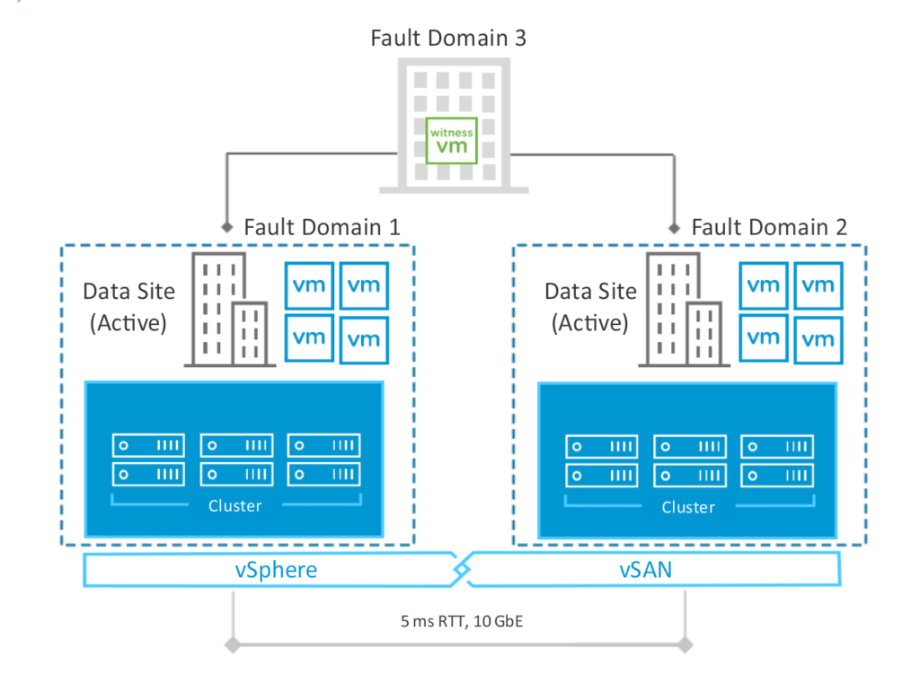
Note: Each data site of the vSAN Stretched Cluster is a Fault Domain. Basically, a Fault Domain is a “logical domain” to determine how resilient or how many failures it is possible to tolerate, for example. The Fault Domain concept exists on all types of vSAN Clusters!
Below, we can see the vSAN Stretched Cluster topology. We have 3 different sites (two data sites and one site for Witness – we will talk about the Witness later). Following, we can see the Stretched Cluster topology:
What is the Data Site?
As we said, both sites that we are using to host ESXi hosts are data sites. On each site, ESXi hosts are responsible to run the workloads (virtual machines). For disaster recovery purposes, however, is highly recommended that both sites are geographically distanced.
Additionally, It is a requirement there is a high network link (minimum of 10 Gbps) with low latency (under 5 ms) for ESXi hosts’ communication between data sites.
What is the Witness Site?
For a vSAN Stretched Cluster, a Witness Host or Witness Appliance is a requirement. The Witness is responsible to store the witness objects for all vSAN Objects inside the Stretched Cluster. For example: when a vmdk file will be stored in a vSAN Datastore on a Stretched Cluster, by default, the components for this vmdk object will be stored as described below:
— One component will be stored in Data Site A (or Preferred Site)
–The other will be stored in Data Site B (or Secondary Site)
–And the last will be stored in Witness Site
So, in this case, the Witness Host is very important to maintain all vSAN Objects’ compliance through the vSAN Policy. Also, it determines what data site is still available in case of a data site failure.
It is a requirement for a communication link with a minimum of 100 Mbps. Related to the latency links under 200 ms of latency for ESXi hosts’ communication with the Witness Host.
Such as a lab environment, we don’t have different sites to implement the vSAN Stretched Cluster. So, in this case, we will create the vSAN Stretched Cluster in a lab environment using the same site for it.
How to install the vCenter Server
Firstly, we highly recommend installing and configuring the vCenter Server Appliance. We have an article that explains how to do it. Click HERE to read the article. We installed the vCenter Server Appliance on the VMware Workstation, but, if you intend to install it in another environment, no problem. I believe that the steps can help you do it too.
How to install the ESXi Host
The next step is to prepare the ESXi hosts for creating the vSAN Stretched Cluster. Like vCenter Server, we have an article that explains how to install and how to configure the ESXi host. Click HERE to read the article. We installed the ESXi host in a lab environment on VMware Workstation, but, if you intend to install it in another environment, no problem. I believe that the steps can help you do it too.
After installing each ESXi host (4 in total), the disk layout for each ESXi host should be:
- 1 disk of 10 GB (ESXi OS)
- 1 disk of 10 GB (Host’s local datastore)
- 1 disk of 12 GB (for the Cache Layer of the vSAN)
- 1 disk of 32 GB (for the Capacity Layer of the vSAN)
Related to the network interfaces, we can use two or four network interfaces. In this article, we are using two network interfaces on each ESXi host.
Downloading the Witness Appliance
As we said before, the vSAN Stretched Custer needs the Witness Host to work. It is a requirement!
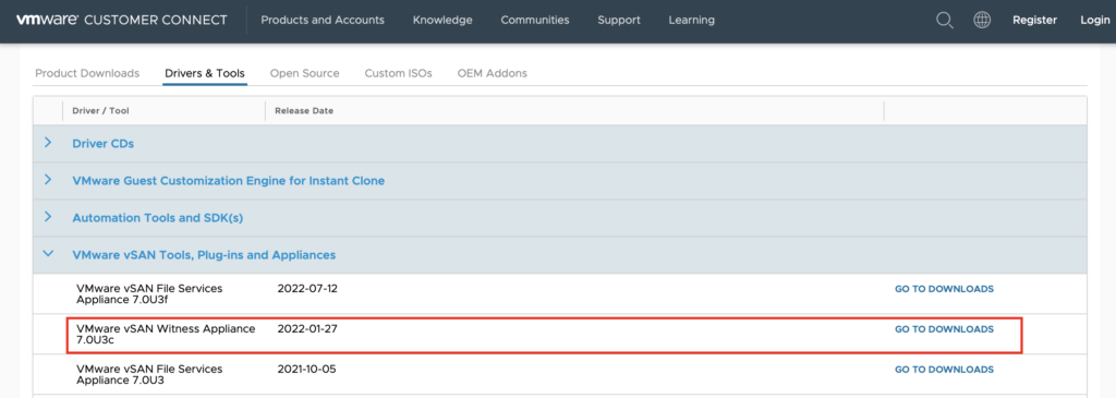
The first step is to download the Witness Appliance OVA file. We can do that by accessing the below link (to realize the download, however, it is necessary to log in on the VMware Customer Connect Site. If you don’t have an account, it will necessary to create that before downloading the file):
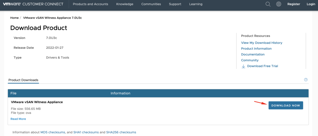
After clicking on “Download Now”, it will necessary to put Credentials:
Note: Store the Witness Appliance OVA file in a place of your preference. We will use this file to deploy the Witness Appliance VM.
Creating the Datacenter Object for the Witness in the vCenter Server
As a recommendation, it is necessary running the Witness Appliance on a third site (not running in the data sites). For lab purposes, we are running all VMs together. But, we will create the logical structures to segment the data sites to the Witness Site.
Firstly, it is necessary to create a Datacenter Object in the vCenter Server dedicated to the Witness Appliance. In the real world, this Datacenter is necessary too, but the computing resources placed on this Datacenter are located on the third site.
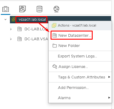
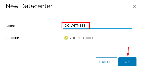
So, open the vSphere Client, select the vCenter Server –> Right Click –> New Datacenter –> The Datacenter name is “DC-WITNESS”:
Creating the Datacenter and Cluster Object for the vSAN Cluster in the vCenter Server
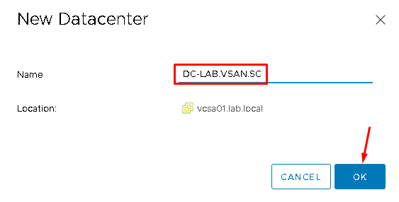
For creating the vSAN Datacenter Object, select the vCenter Server –> Right Click –> New Datacenter –> On the Datacenter name put “DC-LAB.VSAN.SC“:
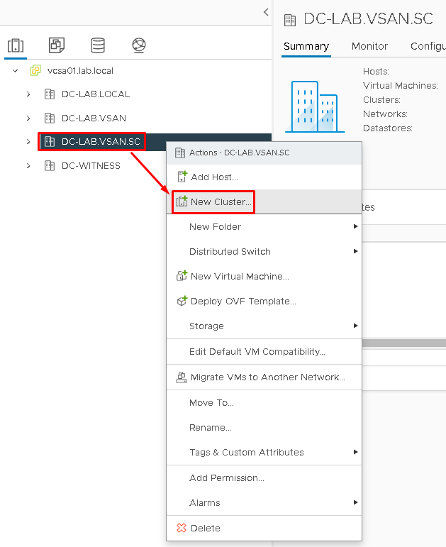
After that, to create the Cluster Object, select the Datacenter that we created before –> Right Click –> New Cluster:
On the Cluster Name, type “CL-LAB.VSAN.SC” and maintain all services disabled (however, we will enable the services as needed):
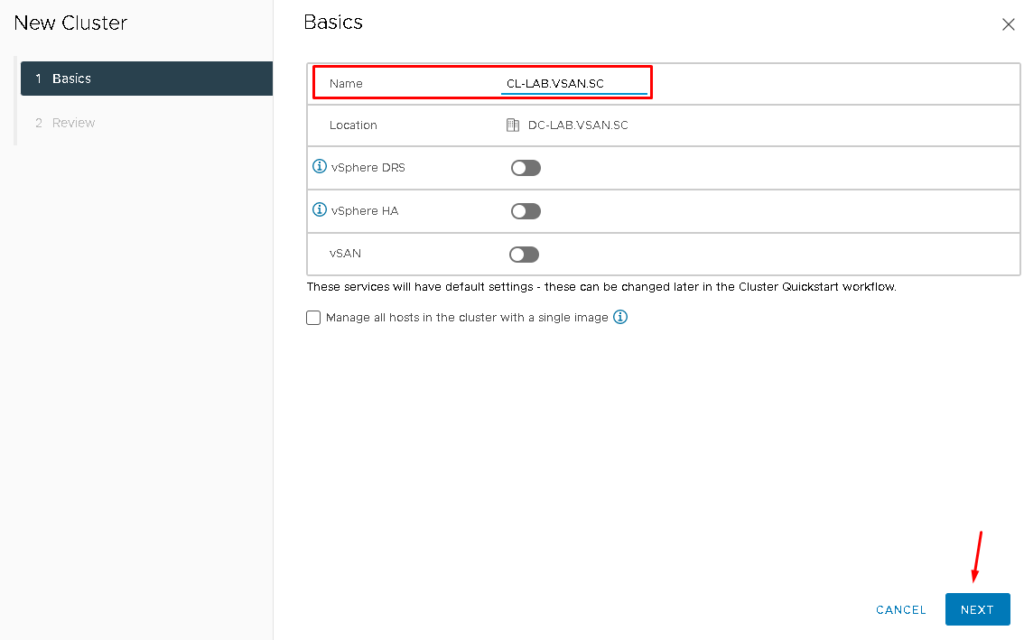
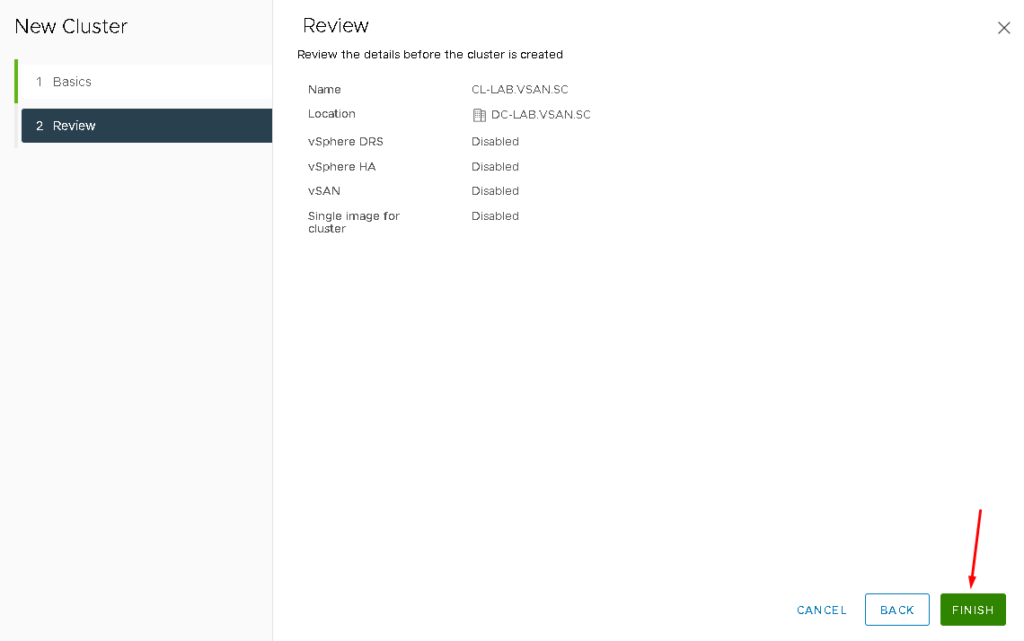
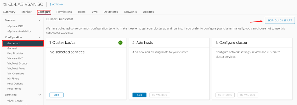
Select the cluster –> Configure –> Under Configuration, Quickstart –> Select SKIP QUICKSTART.
Basically, QuickStart is a Wizard that helps to configure the cluster. We will not use it to configure our cluster. We will configure the options as necessary manually:

Creating the vSphere Distributed Switch
We will create a vSphere Distributed Switch for using it on the vSAN Cluster. It is highly recommended to use the vSphere Distributed Switch (VDS) than vSphere Standard Switch (VSS). With VDS, we have a lot of features such as Network I/O Control, Traffic Filter in both directions (In/Out), Management centralized on the vCenter Server and others.
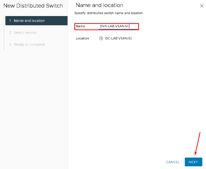
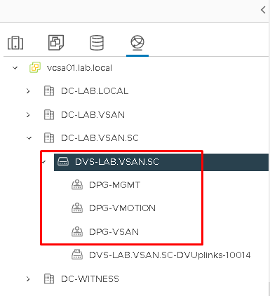
In our lab, for instance, the VDS is “DVS-LAB.VSAN.SC” (you can change the VDS name for anyone as you like).
Select the Networking tab on the vSphere Client and then, select the Datacenter Object that we created before –> Righ Click –> Distributed Switch –> New Distributed Switch:
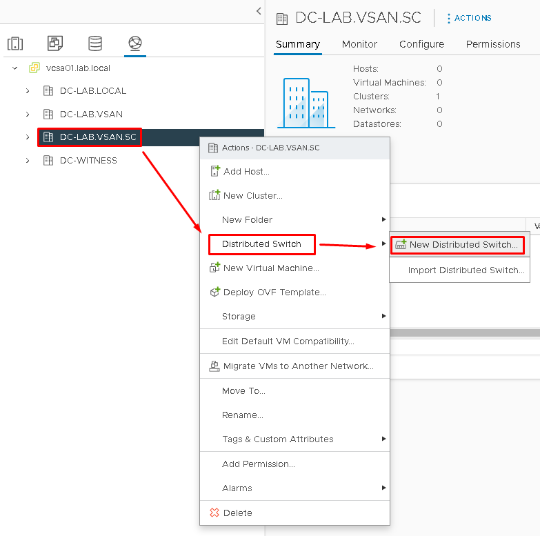
Type the Distributed Switch Name and click on NEXT to continue:
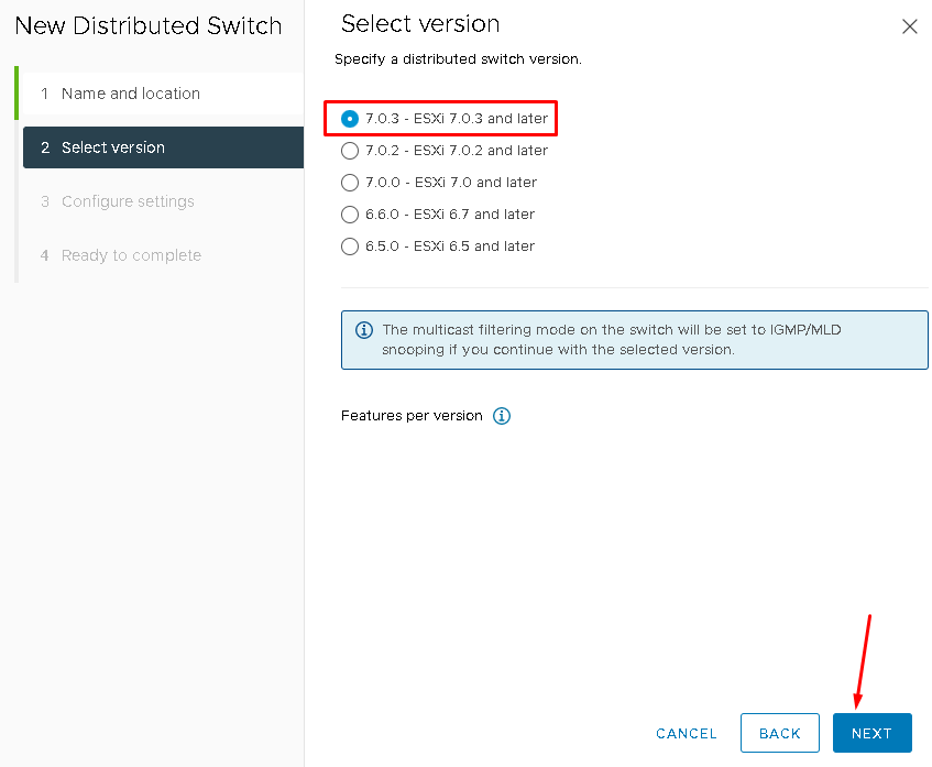
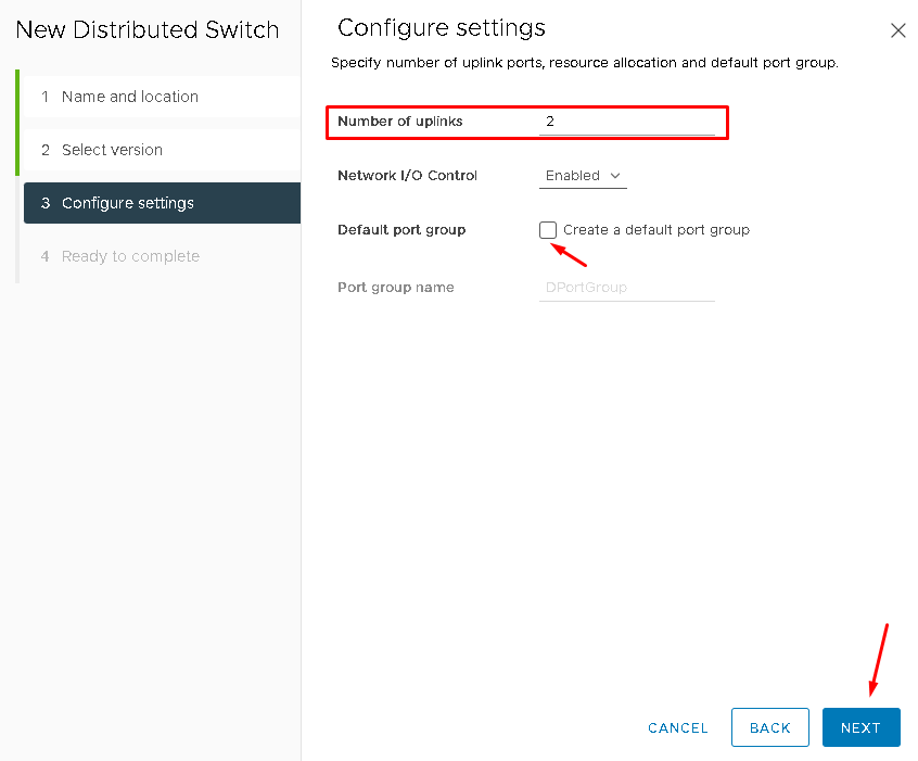
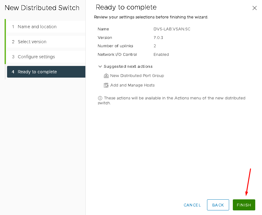
On the “Number of uplinks” change to 2 and unmark the option “Create a default port group”. Click on NEXT to continue and then, click on FINISH to finish the Distributed Switch creation wizard:
Creating the vSphere Distributed Port Groups
We will create some vSphere Distributed Port Group that we are using on our environment.
We are creating the following Distributed Port Groups:
— DPG-MGMT: DIstributed Port Group for Management Traffic
— DPG-VSAN: Distributed Port Group for vSAN Traffic
— DPG-VMOTION: DIstributed Port Group for vMotion Traffic
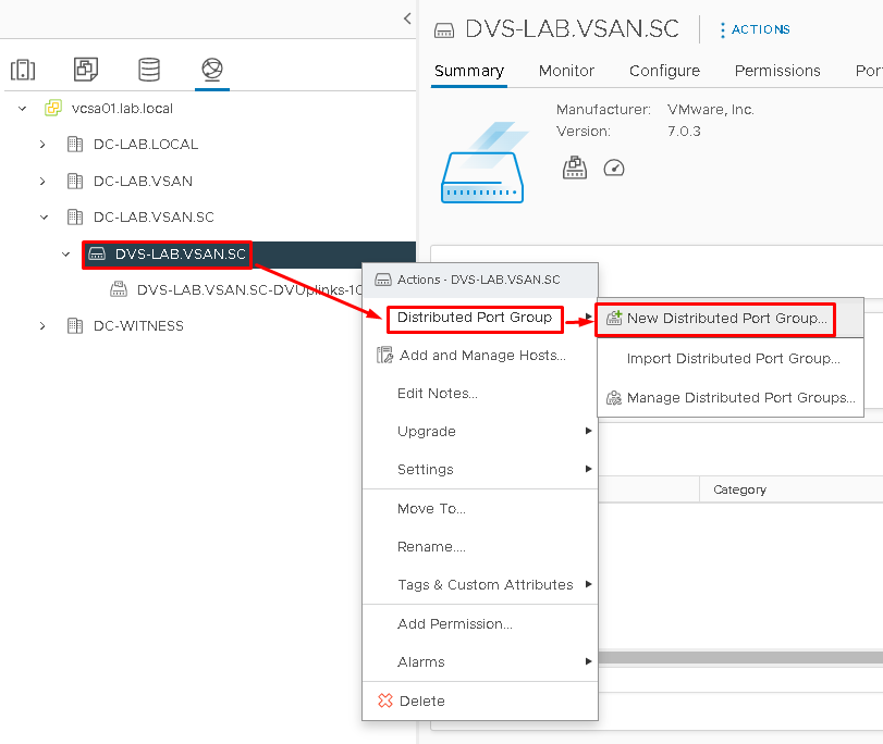
To create the Port Group, select the Distributed Switch that we created before –> Right Click –> Distributed Port Group –> New Distributed Port Group:
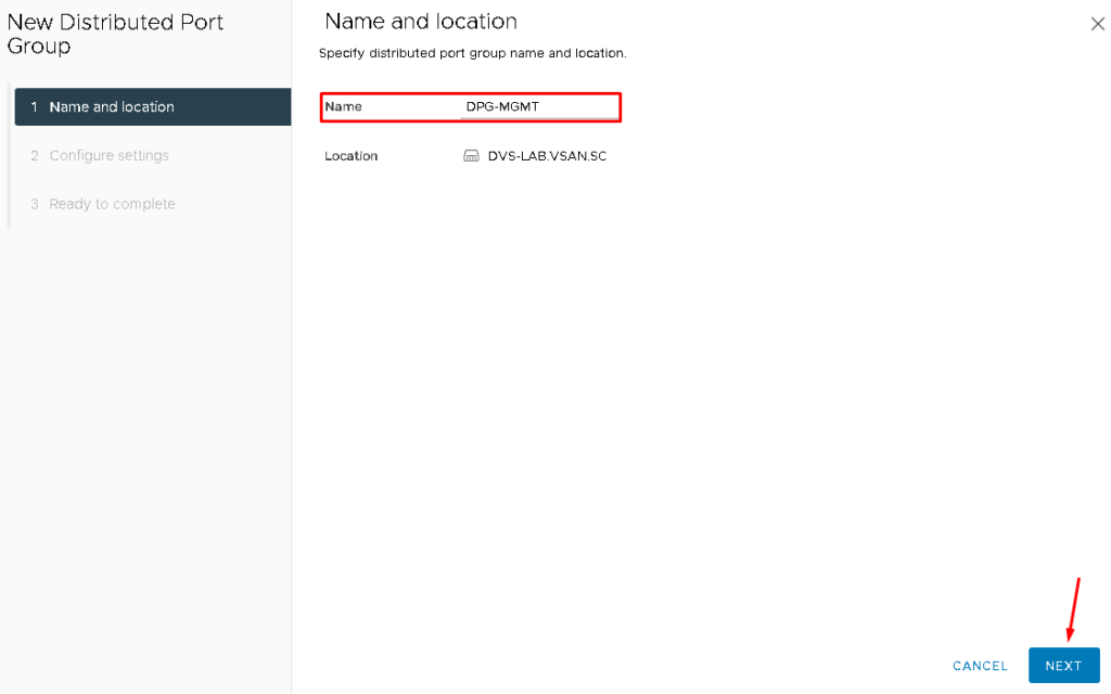
Type the Distributed Port Group Name. In this case, we are creating the Port Group for Management Traffic:
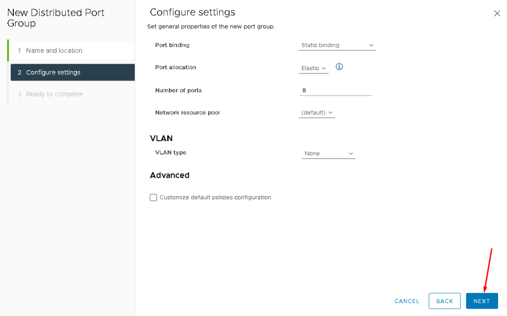
Maintain all options with default values and click on NEXT –> FINISH to finish the Port Group creation assistant:
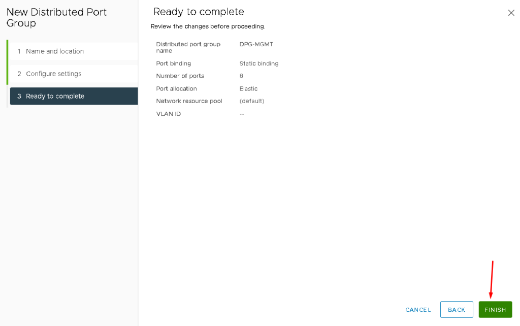
Note: Additionally, do the same steps to create Port Groups for vSAN and vMotion Traffic:
Adding the ESXi Hosts in the vCenter Server
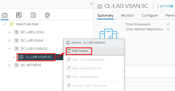
So, at this point, we need to add each ESXi host to the cluster that we created before. To do it, select the cluster –> Right Click –> Add Hosts:
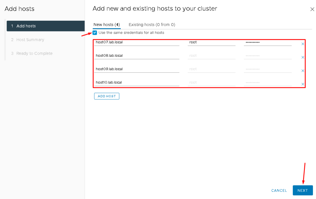
Here, we are adding all ESXi hosts in the same step. Mark the option “Use the same credentials for all hosts” if the root password is the same for all ESXi hosts. Click on NEXT to continue:
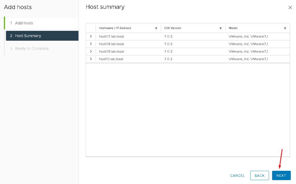
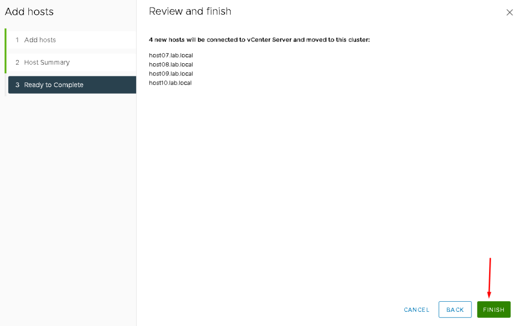
Click on FINISH to finish the Add Host assistant:

Adding the ESXi Hosts in the Distributed Switch
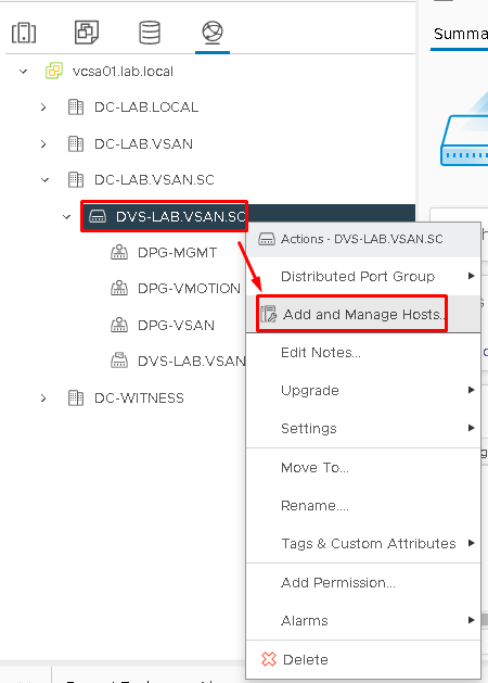
After we added all ESXi hosts to the cluster, we need to add each ESXi in the Distributed Switch. On the vSphere Client, select the Networking Tab. Then, select the Distributed Switch –> Add and Manage Hosts:
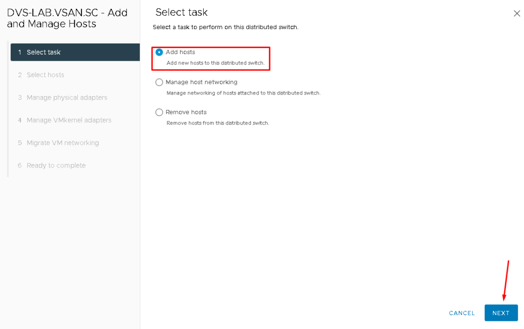
Click on “Add hosts” and NEXT:
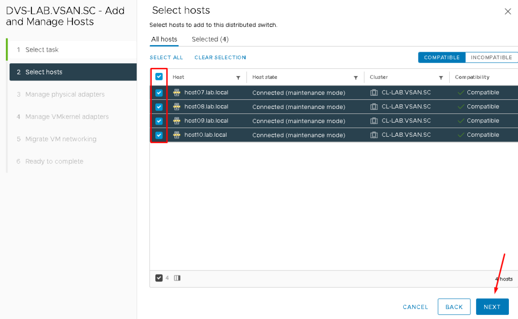
Select all ESXi hosts available. In our case, there are four ESXi hosts:
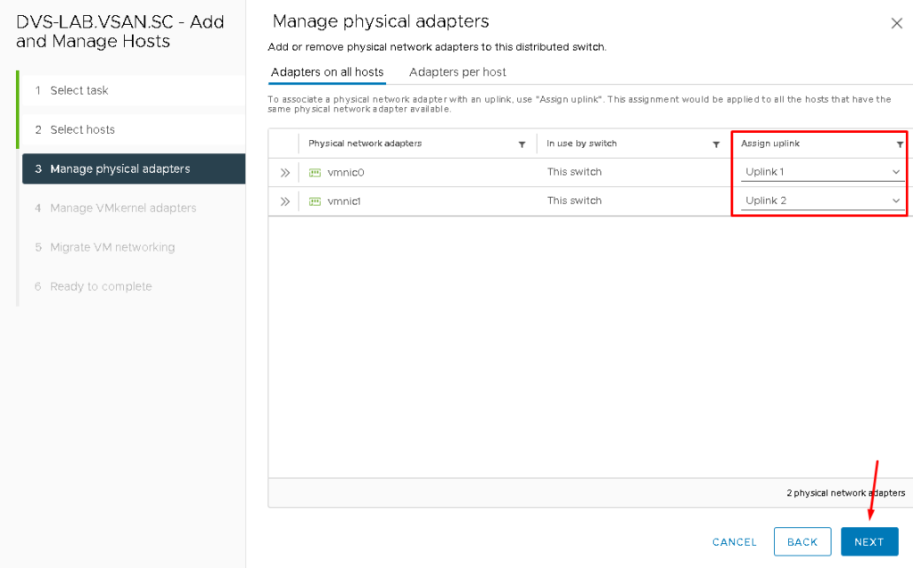
Here is an important step. We need to assign what vmnic (physical interface) interface will be assigned to what uplink of the distributed switch.
In our environment, the assignment is being realized such described below:
- vmnic0 –> Uplink 1
- vmnic1 –> Uplink 2
After that, click on NEXT to continue:
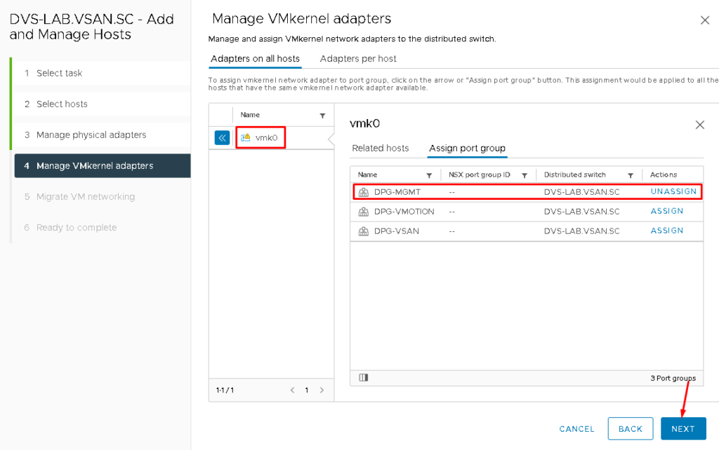
The next step is necessary to assign the Management VMkernel adapter to the new Port Group (in this case, the new Distributed Port Group is provided by the Distributed Switch).
Select the VMkernel “vmk0” –> Assign port group –> Under “DPG-MGMT” click on ASSIGN. After you do it, the action “UNASSIGN” will show, proving that the assignment has been done.
Click on NEXT to continue:
NEXT –> FINISH:
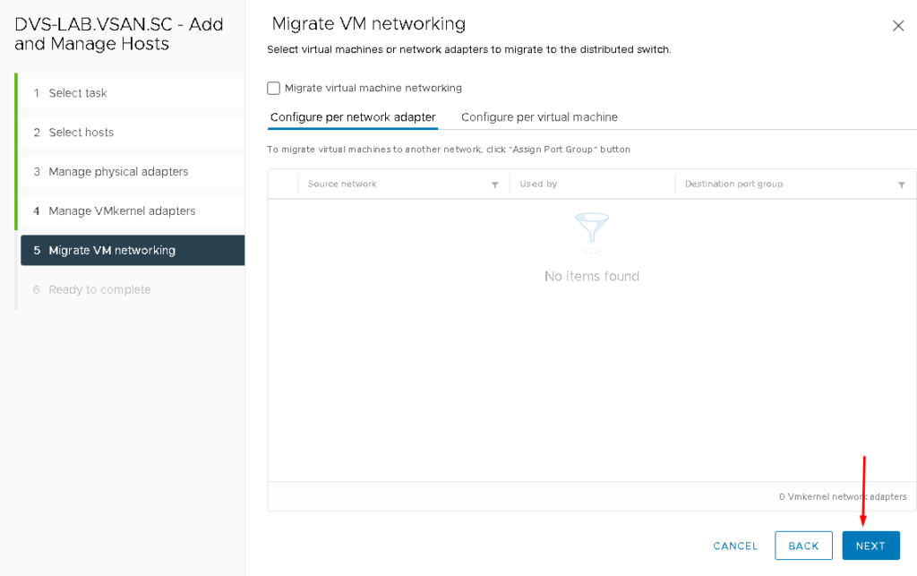
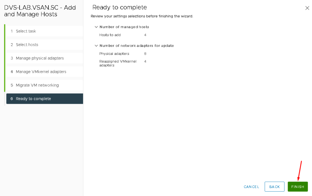
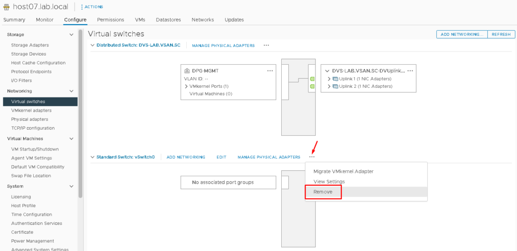
At this point, all ESXi hosts are part of the Distributed Switch. The Standard Switch called “vSwitch0” can be removed. To do it, click on the three dots –> Remove (do it on all ESXi hosts) under the vSwitch0:

Creating the VMKernel Interfaces on the ESXi Hosts
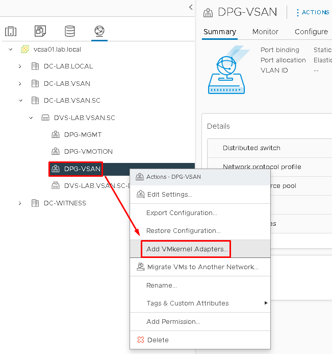
A VMkernel interface is a layer 3 interface that is used by the ESXi host. We need to create the vSAN VMkernel and vMotion VMkernel. To create the vSAN VMkernel interface, select the vSAN Distributed Port Group –> Right Click –> Add VMKernel Adapters:
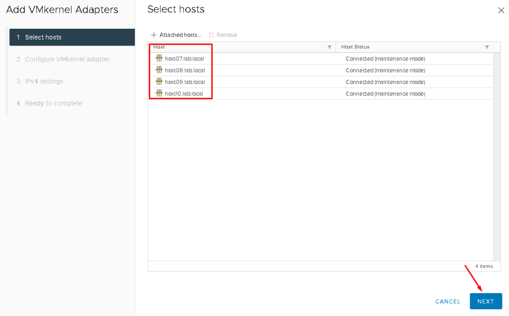
Later, attach all hosts to add the VMkernel interface:
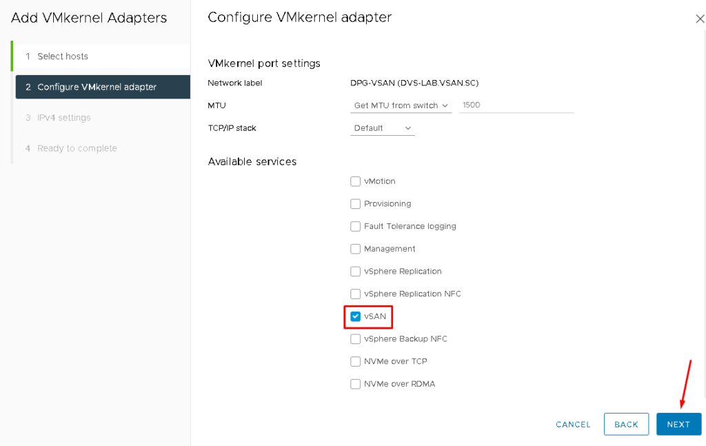
On the “Available services“, mark the service vSAN and click on NEXT to continue:
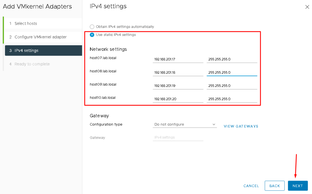
On IPv4 settings, mark the option “Use static IPv4 settings” and define the IP settings for each ESXi host to communicate on the vSAN network. After that, click on NEXT to continue:
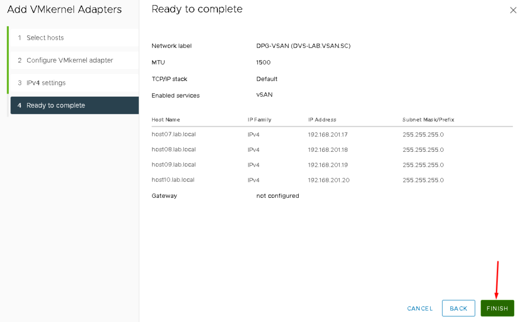
Then, click on FINISH to finish the VMkernel creation wizard:
To confirm if the vSAN VMKernel was created, select each ESXi host –> Configure –> Under Networking, select VMKernel adapters. The vmk1 is used in the vSAN network:

Note: Repeat the same steps to create the vMotion VMkernel. Obviously, for that VMkernel, it is necessary to use a different subnet and mark the vMotion service. The vmk2 is used in the vMotion network:

Testing the Communication Between ESXi Hosts in the vSAN Network
From the host’s console or SSH session, we can check the communication in the vSAN Network:
To list all VMkernel interfaces on the ESXi host:
esxcli network ip interface ipv4 get

To check the communication from this ESXi host to other hosts on the vSAN network, for instance, the command is below:
vmkping -I vmk1 IP_VSAN -s 1472 -d
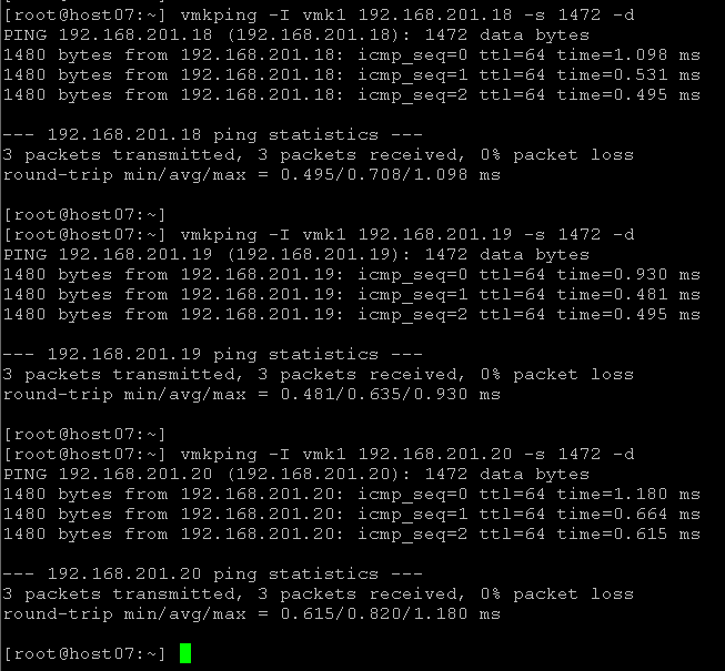
Where:
- 192.168.201.18 –> vSAN IP for the host08
- 192.168.201.19 –> vSAN IP for the host09
192.168.201.20 –> vSAN IP for the host10 - vmkping -I vmk1 –> The source interface for ping packets
- -s 1472 –> Size of the packet
- -d –> Avoid packet fragmentation
Deploying the Witness Appliance from OVA
As we don’t have a dedicated ESXi host to run the Witness Appliance, we will deploy the Witness Appliance in one data site (Preferred, for example), and later, we will add the Witness Appliance into Witness Datacenter “DC-WITNESS”.
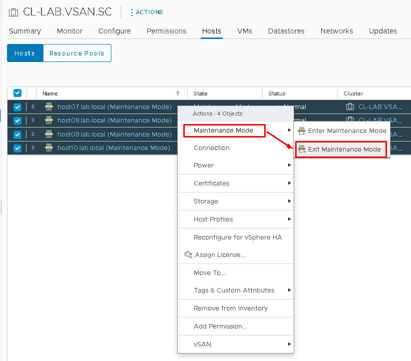
Firstly, if ESXi hosts are in maintenance mode, remove them from maintenance mode:
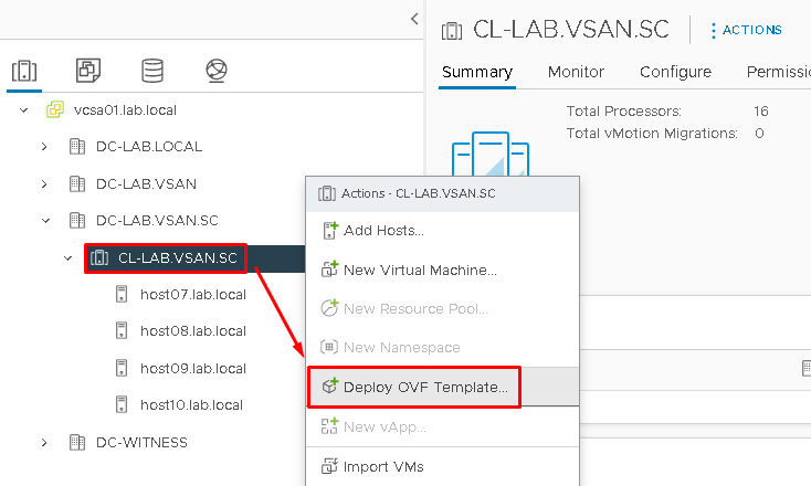
For deploying the Witness Appliance, select the Cluster Object that we created before –> Right Click –> Deploy OVF Template:
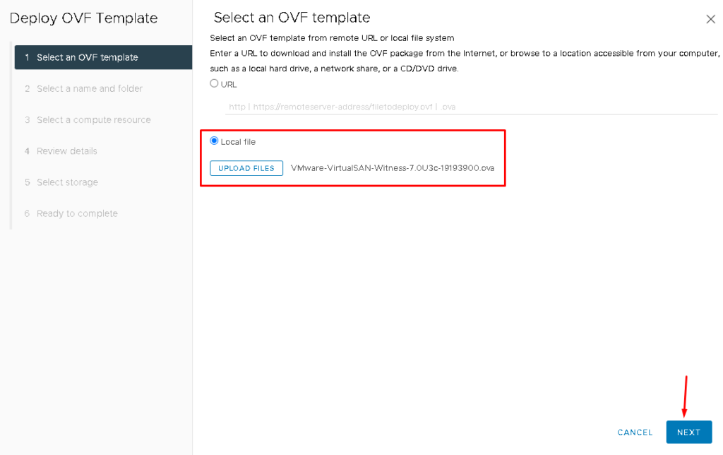
Click on “UPLOAD FILES” and then search for the Witness OVA file. Click on NEXT to continue:
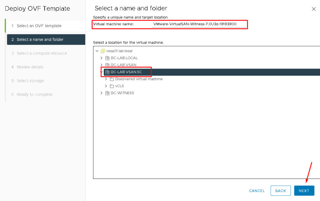
Type the Virtual Machine name. In this case, we are maintaining the default name. Later, select the Datacenter Object that this Virtual Machine will be using.
Click on NEXT to continue:
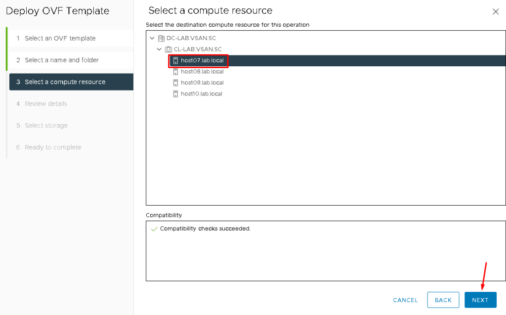
Select the destination compute resource for the Witness Appliance VM. In this case, we are using the first ESXi host to run this Virtual Machine. Then, click on NEXT to continue:
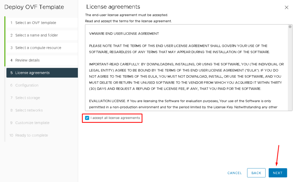
Mark the option “I accept all license agreements” and click on NEXT:
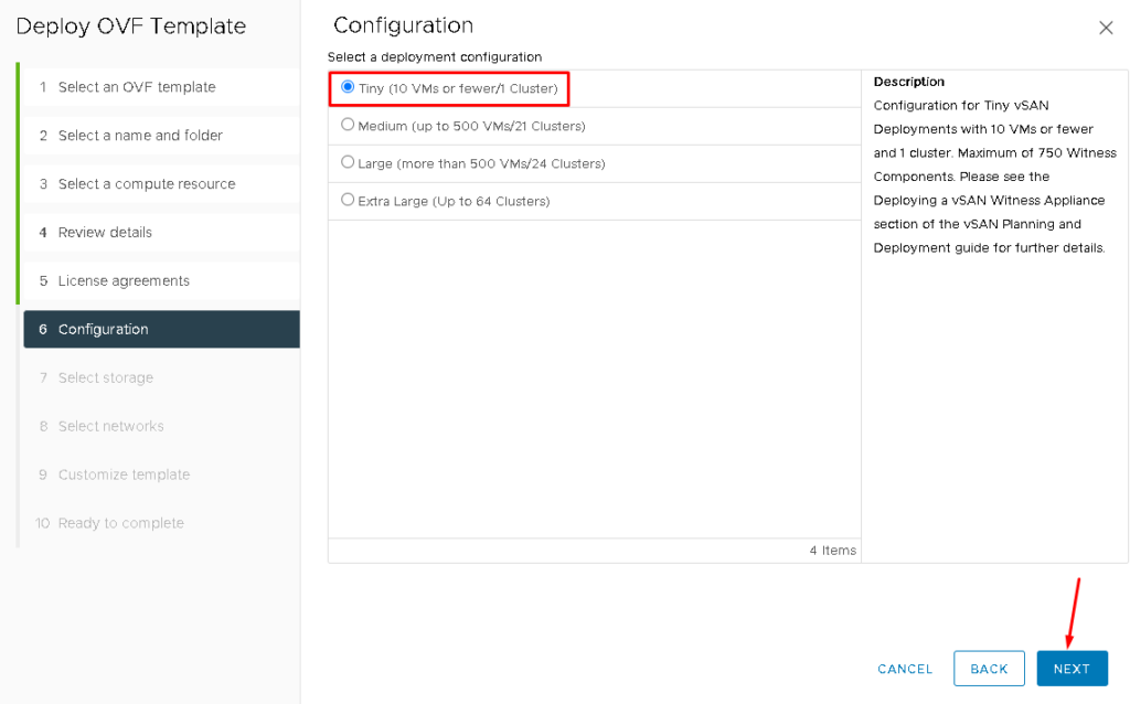
Here, it is necessary to select the size of the Witness Appliance.
Each size is indicated for some situations. For example, the Tiny size is indicated for small environments. It supports 1 cluster and 10 VMs at the maximum – for a lab environment, this size is sufficient:
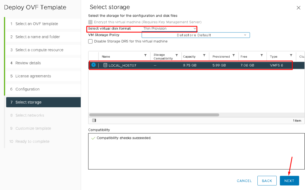
As we don’t have network storage yet, we are using the local datastore for the ESXi host.
On “Select virtual disk format” select “Thin Provision” and then select the local datastore, such as shown in the picture below.
Click on NEXT to continue:
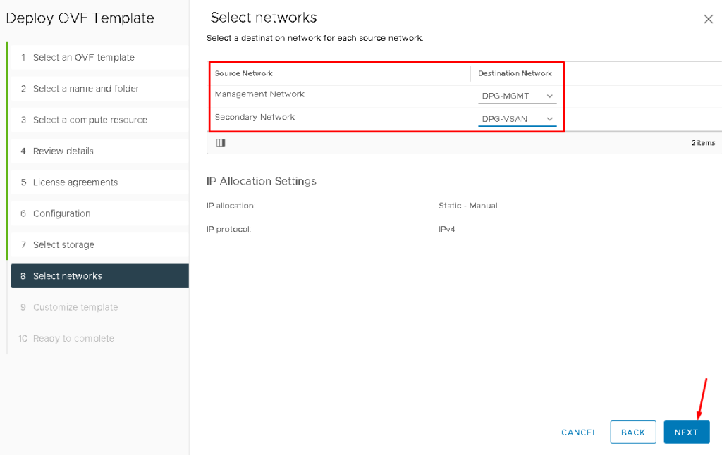
The Witness Appliance has two network interfaces:
- Management Network: Dedicated to Witness Appliance management
- Secondary Network: Dedicated to the Traffic with the ESXi hosts (vSAN Network)
In this case, the Management Network is being mapped to the “DPG-MGMT” Port Group and the Secondary Network is being mapped to the “DPG-VSAN” Port Group.
Click on NEXT to continue:
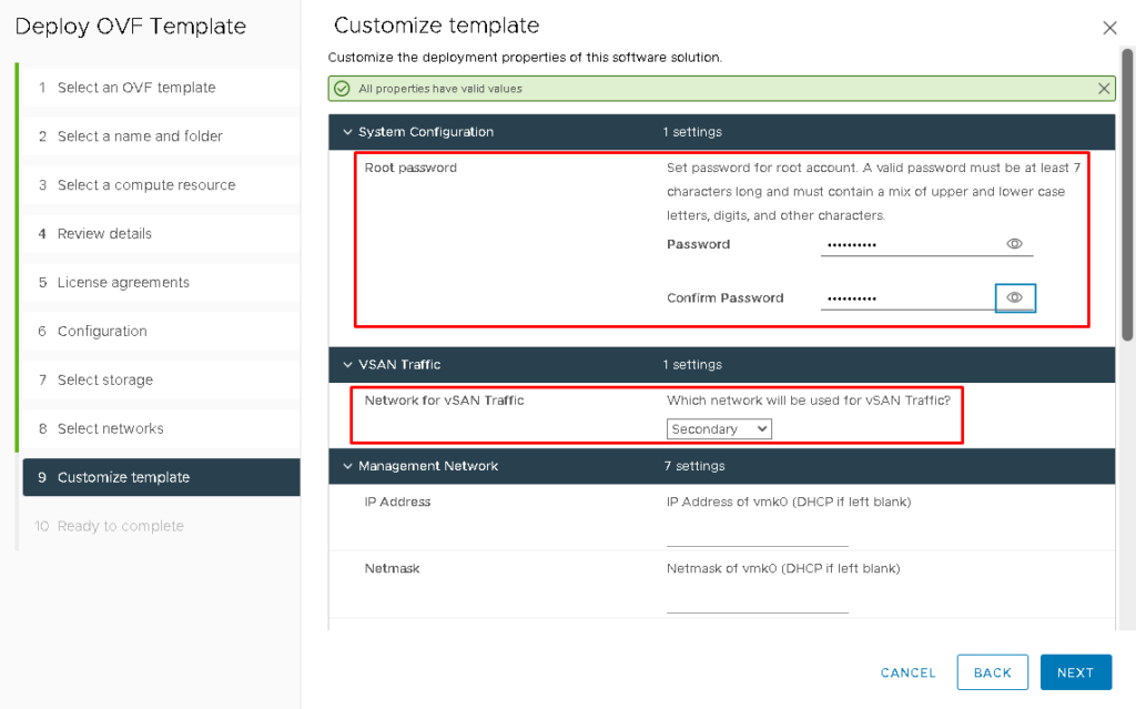
Define the root password and determine which interface will use for the vSAN Traffic. In this case, we are using the “Secondary” interface for vSAN Traffic.
Don’t Click on NEXT yet:
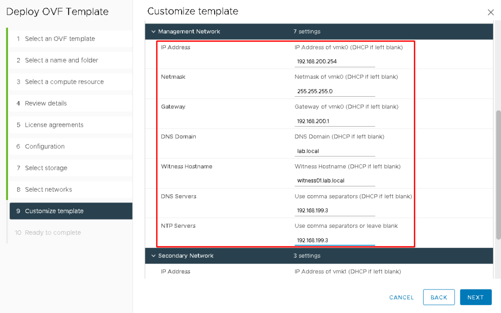
Type the IP address, Netmask, Gateway, DNS Domain, Witness Hostname, DNS Server, and NTP Server for the Witness Appliance Management Interface:
Don’t Click on NEXT yet:
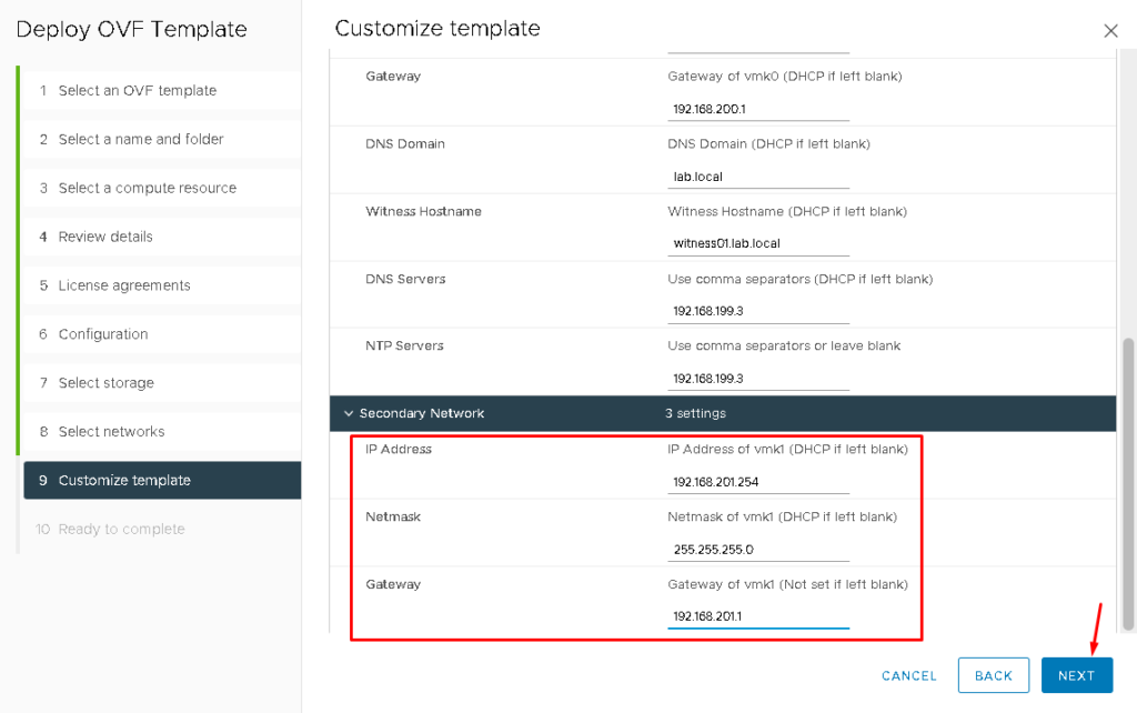
Define the IP address, Netmask, and Gateway for the Secondary Network (vSAN).
Now, click on NEXT to continue:
Click on FINISH for starting the Witness Appliance deployment:
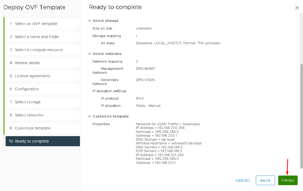
After a few minutes, the deployment will finish.
So, select the Witness Appliance VM and click on Power On:
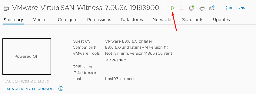
In our lab, we received an error while we were trying to power on the Witness Appliance VM.

Note: This error is related to the lack of disk space in the local datastore of the ESXi host. To solve this issue, we put the ESXi host in maintenance mode –> Shutdown the ESXi host. We increased the disk used for the local datastore and later we could power on the Witness Appliance VM normally:
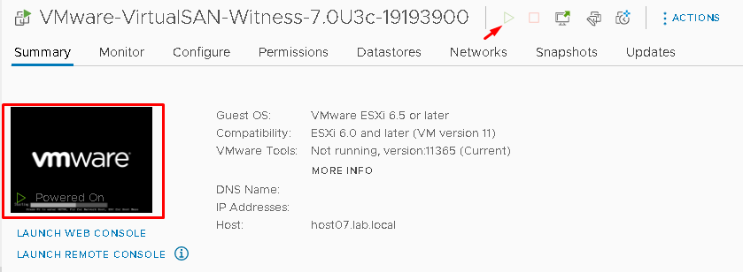
The Witness Appliance is an ESXi host, prepared to be the Witness Appliance – It is not possible to run any Virtual Machine in the Witness Appliance, for example:
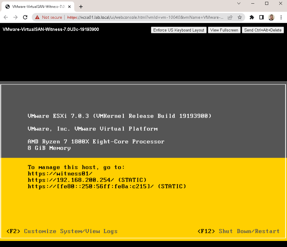
Testing the Communication Between ESXi hosts and Witness Appliance
From the host’s console or SSH session, we can check the communication in the vSAN Network:

Where:
- 192.168.201.254 –> vSAN IP for the Witness Appliance
- vmkping -I vmk1 –> The source interface for ping packets
- -s 1472 –> Size of the packet
- -d –> Avoid packet fragmentation
Adding the Witness Appliance VM to the Witness Datacenter
After the Witness Appliance VM deployment, we need to add this VM to the Witness Datacenter that we created before. As we said, this VM is an ESXi host. So, we can add this ESXi host normally in the vCenter Server.
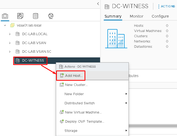
Select the Witness Datacenter Object –> Right Click –> Add Host:
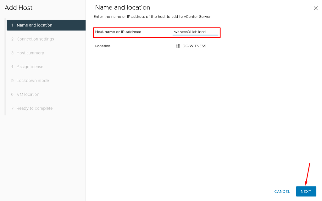
Type the hostname, FQDN, or IP address of the Witness Appliance VM:
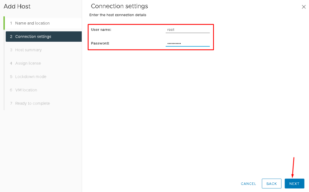
Put the root credentials:
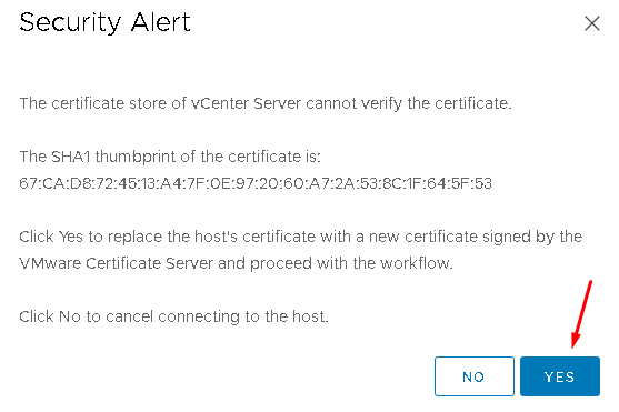
Confirm the thumbprint alert for the Witness Appliance VM certificate:
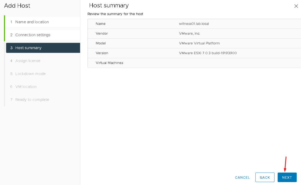
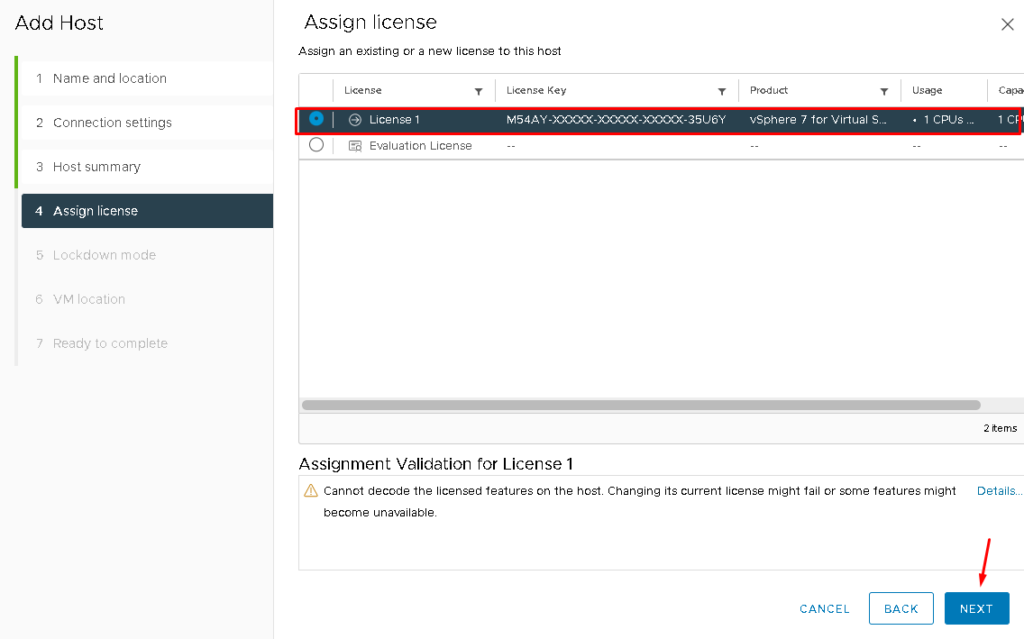
To use the Witness Appliance, a valid license is possible to select. This license is embedded in the Witness Appliance VM.
Select “License 1” and then click on NEXT to continue:
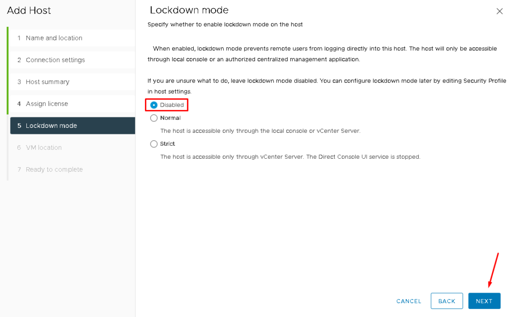
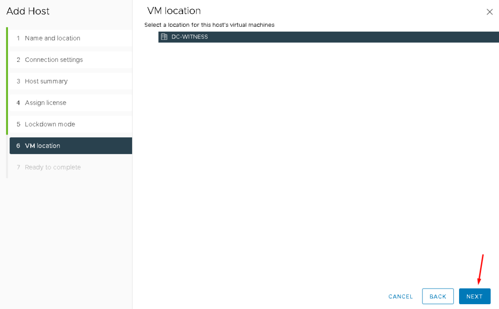
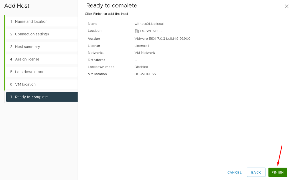
Click on FINISH to finish the add host assistant:

Creating the vSAN Stretched Cluster
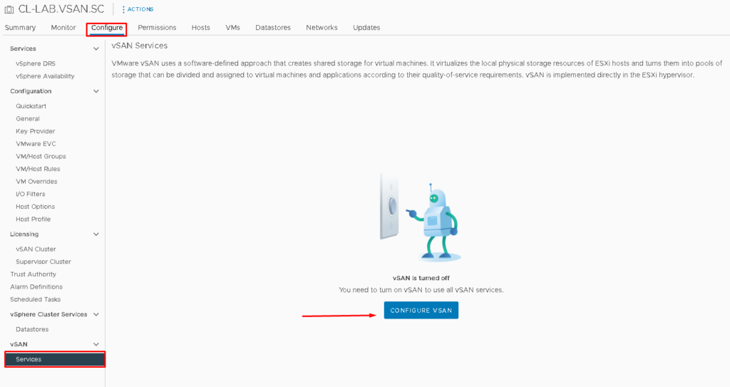
To enable the vSAN service, select the Cluster that we created before –> Configure –> Under vSAN, select Services –> CONFIGURE VSAN:
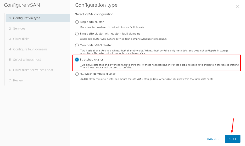
Select “Stretched cluster” and click on NEXT to continue:
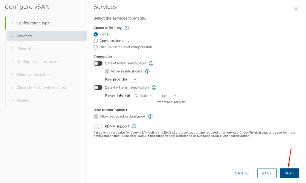
On Services, maintain all options with default values. Click on NEXT to continue:
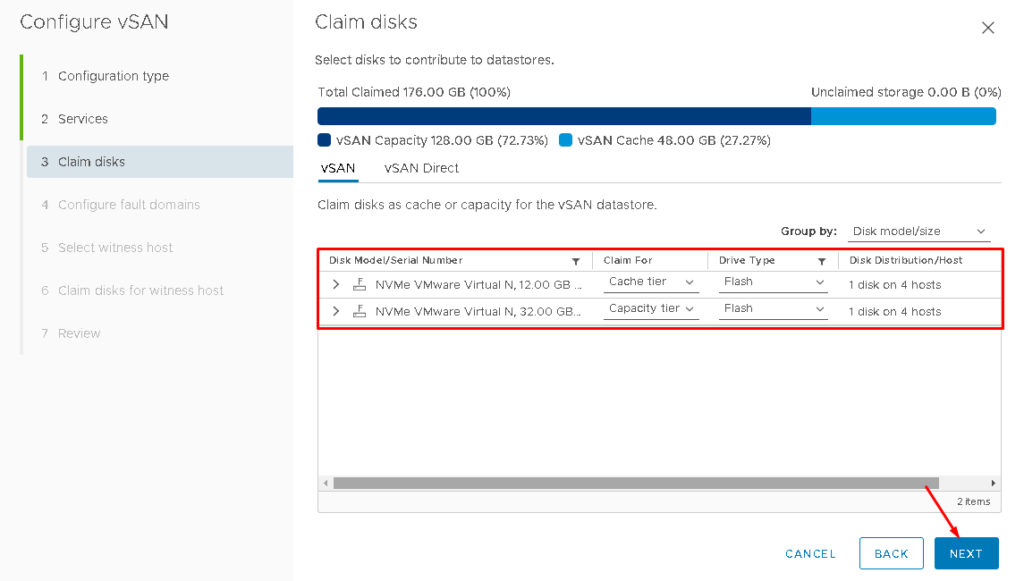
On Claim disks, we need to select what disk will be used for the cache layer and what disk will be used for the capacity layer. By default, the smaller disk is selected for the cache layer. Review that and adjust it if necessary. After that, click on NEXT to continue:
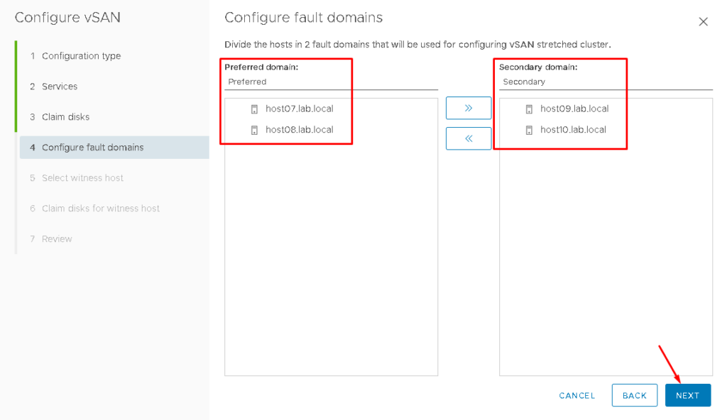
As we said, each site is a Fault Domain.
Here, we need to select what ESXi hosts will be on the Preferred Site and what ESXi hosts will be on the Secondary Site (each site is a Fault Domain):
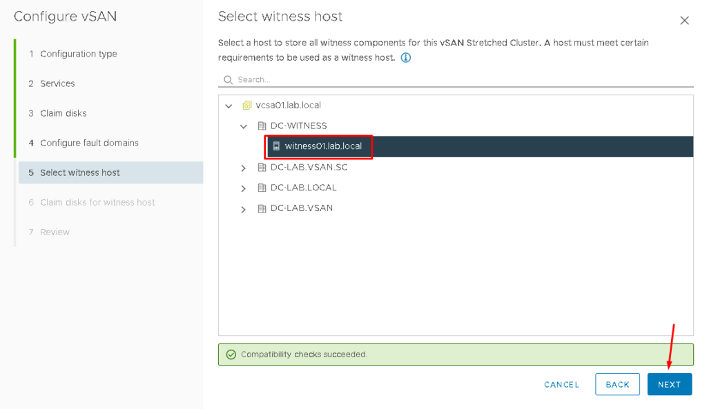
Select the Witness Host and click on NEXT to continue:
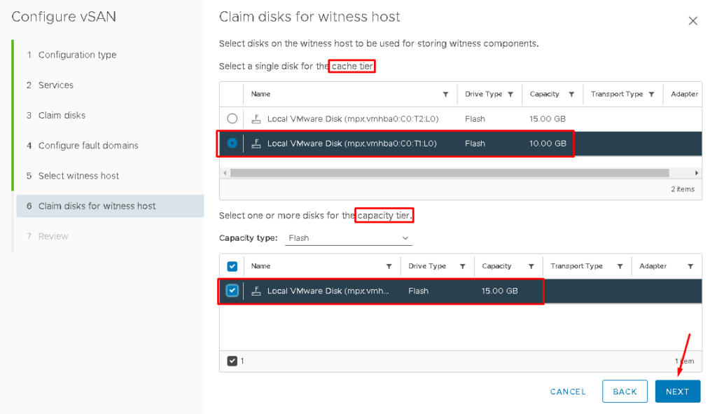
Select the cache disk and capacity disk for the Witness Host’s Disk Group:
Click on FINISH to finish the vSAN service enabling wizard:
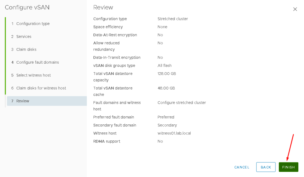
After a few seconds, the vSAN Stretched Cluster will be ready:
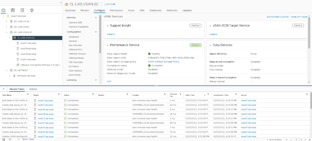
To check if the vSAN service was enabled, select the Cluster –> Monitor –> Under vSAN, select Skyline Health –> And click on RETEST:
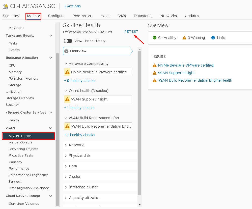
Note: The vSAN Skyline Health is a KEY tool to monitor the health of all vSAN Cluster. Definitely, it is the first point of checking the health of all vSAN components. In this case, we don’t have any failure or error alarms.
Under Capacity, we can see the vSAN Datastore Capacity:
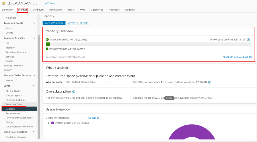
At this point, our vSAN datastore is ready 🙂
We can create VMs and place their objects into the vSAN Datastore!
Analyzing the vSAN Physical Disk Placement for a Virtual Machine
After creating a Virtual Machine and configuring that to use the vSAN Datastore, we can see how the vSAN Objects and Components were placed on the vSAN Datastore.
Select the Virtual Machine –> Monitor –> vSAN –> Physical disk placement:
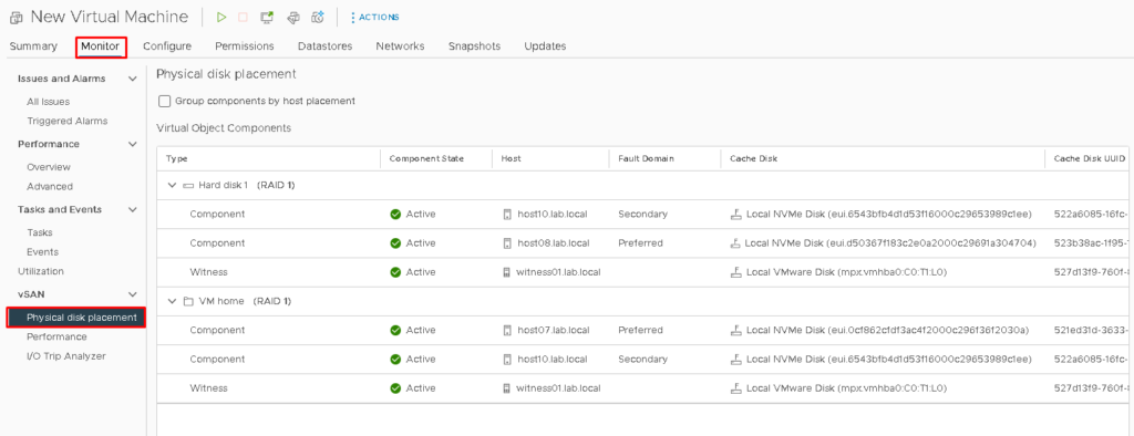
Here, it is possible to see that “Hard Disk 1” is a vSAN Object and that all Components (three components) are using one Host:
- The first component is using the host10 (Secondary Fault Domain)
- The second component is using the host08 (Preferred Fault Domain)
- The last component is using the Witness Appliance Host
This behavior is the same for all vSAN Objects that are using the vSAN Default Storage Policy!