

This hands-on lab shows how to deploy a nested Dell PowerFlex 3.6.4 cluster on VMware vSphere. The environment uses virtual machines to model PowerFlex storage nodes, a five-node MDM cluster, VLAN-separated traffic, a PowerFlex Gateway, a Presentation Server, and Windows and ESXi Storage Data Clients (SDCs).
Lab warning: This is a nested learning environment. It is intended to demonstrate PowerFlex concepts and deployment workflows, not to provide a production design. Virtualizing storage nodes on a single physical ESXi host introduces shared failure domains and does not reproduce the performance, availability, or hardware-validation characteristics of a production PowerFlex system.
If you are new to the platform, read Getting Started with Dell PowerFlex: Architecture and Key Components first. That article explains the roles of the Meta Data Manager (MDM), Storage Data Server (SDS), Storage Data Client (SDC), Storage Data Target (SDT), Storage Data Replication (SDR), and Lightweight Installation Agent (LIA).
PowerFlex Lab Topology
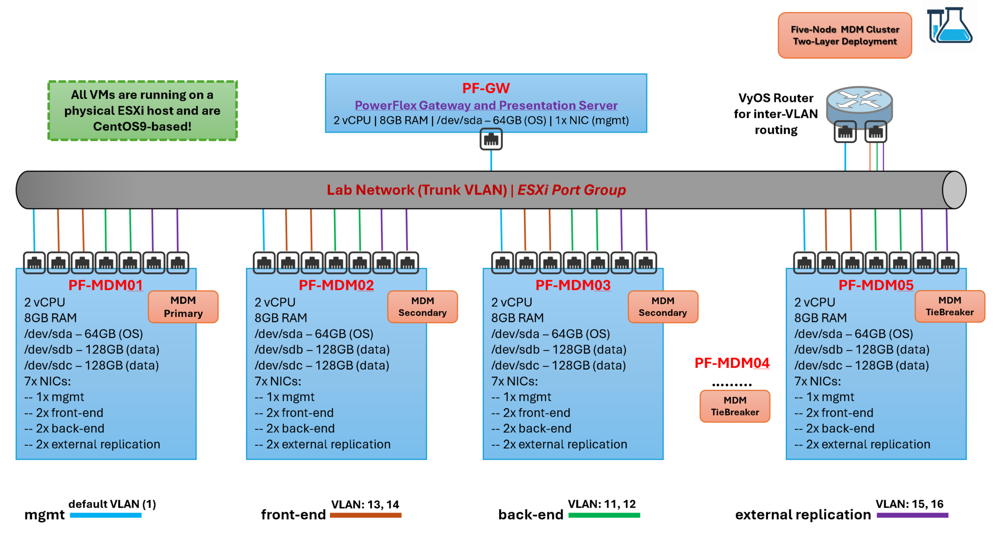
This lab uses PowerFlex 3.6.4 and a set of CentOS-based virtual machines running on an ESXi host. All virtual machines use the same vSphere port group through a standard vSwitch. The topology is deliberately simplified for training.
The five PowerFlex nodes perform two roles:
- They form a five-node MDM cluster.
- They run SDS components and contribute local virtual disks to the PowerFlex storage pool.
Each node has seven virtual network adapters. The design separates management, back-end storage, front-end client, and external replication traffic. In a production deployment, these networks must be designed around validated hardware, switch configuration, redundancy, MTU, failure domains, and Dell’s release-specific requirements.
The lab uses a two-layer layout. Compute resources and storage resources are separated. Storage-only nodes run the SDS and MDM components, while compute-only nodes run the SDC and applications that consume PowerFlex volumes.
The PowerFlex Gateway and Presentation Server are installed on separate virtual machines in the recommended design. They are combined in some lab environments to reduce resource consumption, but this article keeps the roles conceptually separate. The Gateway provides the installer and REST API gateway functions. The Presentation Server provides the management UI and API layer.
A VyOS router provides routing between the isolated lab networks. Use the official VyOS documentation for the router configuration that is specific to your topology and VyOS release:
Before You Start
Prepare the following items before deploying the cluster:
- PowerFlex 3.6.4 installation packages and release notes from the Dell support portal.
- A supported operating system and package combination for every PowerFlex component.
- Five virtual machines for the storage and MDM nodes.
- Separate virtual disks for the SDS devices. Do not place all simulated storage devices on the same datastore if the goal is to test failure behavior.
- A DNS and NTP design that provides stable name resolution and time synchronization.
- A management network, two back-end networks, two front-end networks, and optional replication networks.
- A CSV topology file that matches the IP addresses, hostnames, roles, devices, and package versions used in the lab.
Note: PowerFlex 3.6.4 is a legacy release. Confirm component and operating-system compatibility in the release notes before reproducing this lab. Do not copy package names, drivers, or deployment values from this article into a newer PowerFlex release without checking the current Dell documentation.
Step-by-step to configure the PowerFlex Nodes
1- (Optional)
By default, the network adapters are named with the following taxonomy, for example:
ens192
ens224
ens161
etc….
If you prefer, rename each network interface to an “eth” pattern.
Under the /etc/udev/rules.d directory, create a file “70-persistent-net.rules” and add the following entries:
# Accessing the directory
cd /etc/udev/rules.d/

# Creating the file
vim 70-persistent-net.rules

# Creating the rules to rename each network adapter. Each line is renaming one network adapter:
SUBSYSTEM=="net", ACTION=="add", DRIVERS=="?*", ATTR{address}=="00:50:56:81:ee:a6", ATTR{type}=="1", KERNEL=="ens161", NAME="eth2"
SUBSYSTEM=="net", ACTION=="add", DRIVERS=="?*", ATTR{address}=="00:50:56:81:67:2a", ATTR{type}=="1", KERNEL=="ens162", NAME="eth6"
SUBSYSTEM=="net", ACTION=="add", DRIVERS=="?*", ATTR{address}=="00:50:56:81:6e:6d", ATTR{type}=="1", KERNEL=="ens192", NAME="eth0"
SUBSYSTEM=="net", ACTION=="add", DRIVERS=="?*", ATTR{address}=="00:50:56:81:11:96", ATTR{type}=="1", KERNEL=="ens193", NAME="eth3"
SUBSYSTEM=="net", ACTION=="add", DRIVERS=="?*", ATTR{address}=="00:50:56:81:29:9b", ATTR{type}=="1", KERNEL=="ens225", NAME="eth4"
SUBSYSTEM=="net", ACTION=="add", DRIVERS=="?*", ATTR{address}=="00:50:56:81:01:ed", ATTR{type}=="1", KERNEL=="ens256", NAME="eth1"
SUBSYSTEM=="net", ACTION=="add", DRIVERS=="?*", ATTR{address}=="00:50:56:81:5e:78", ATTR{type}=="1", KERNEL=="ens257", NAME="eth5"
Let’s look at the first line:
SUBSYSTEM==”net”, ACTION==”add”, DRIVERS==”?*”, ATTR{address}==”00:50:56:81:ee:a6″, ATTR{type}==”1″, KERNEL==”ens161“, NAME=”eth2“
The network interface recognized as ens161 is being renamed to eth2. The rule must specify the network interface MAC address.
2- We must check if the system module “8021q” is loaded since we will use VLAN interfaces.
If it is not loaded, use the following command to load the module:
modprobe 8021q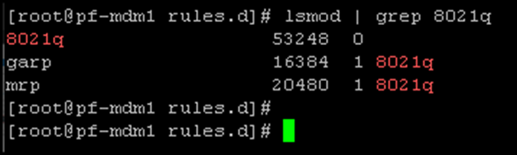
3- Setting up the hostname, management IP address, default gateway, DNS, and NTP server:
# Configuring the hostname:
echo "pf-mdm1" > /etc/hostname

# Configuring the management network interface, setting up the IP, network mask, network gateway, and the DNS server:
nmcli connection modify eth0 ipv4.method manual ipv4.addresses 192.168.255.101/24
nmcli connection modify eth0 ipv4.gateway 192.168.255.1
nmcli connection modify eth0 ipv4.dns 192.168.255.3

# Configuring the NTP (replace 192.168.255.3 to your NTP server IP):
sed -e s/"pool 2.centos.pool.ntp.org iburst"/"pool 192.168.255.3 iburst"/g /etc/chrony.conf
systemctl enable chronyd

# Activating the eth0 network interface and reboot the system:
nmcli connection up eth0
rebootNote: The “nmcli” network utility automatically saves the network config under the directory /etc/NetworkManager/system-connections/, as we can see in the following picture:

This “block” of configuration is for the first node. Do the same for the other nodes, changing the unique values for each one!Configuring the “back-end” Interfaces
4- Configuring the back-end interfaces.
In our case, the physical network interfaces eth1 and eth2 will be used for the back-end traffic. Under each network interface, we will use VLAN 11 and 12, respectively:
eth1 –> vlan11 –> 10.10.11.0/24
eth2 –> vlan12 –> 10.10.12.0/24
# Configuring the vlan11:
nmcli connection add type vlan ifname vlan11 con-name vlan11 dev eth1 id 11
nmcli connection modify vlan11 ipv4.method manual ipv4.addresses 10.10.11.11/24
nmcli connection up vlan11

# Configuring the vlan12:
nmcli connection add type vlan ifname vlan12 con-name vlan12 dev eth2 id 12
nmcli connection modify vlan12 ipv4.method manual ipv4.addresses 10.10.12.11/24
nmcli connection up vlan12
Configuring the “front-end” Interfaces
5- Configuring the front-end interfaces.
In our case, the physical network interfaces eth3 and eth4 will be used for the front-end traffic. Under each network interface, we will use VLAN 13 and 14, respectively:
eth3 –> vlan13 –> 10.10.13.0/24
eth4 –> vlan14 –> 10.10.14.0/24
# Configuring the vlan13:
nmcli connection add type vlan ifname vlan13 con-name vlan13 dev eth3 id 13
nmcli connection modify vlan13 ipv4.method manual ipv4.addresses 10.10.13.11/24
nmcli connection up vlan13

# Configuring the vlan14:
nmcli connection add type vlan ifname vlan14 con-name vlan14 dev eth4 id 14
nmcli connection modify vlan14 ipv4.method manual ipv4.addresses 10.10.14.11/24
nmcli connection up vlan14
Note: The cluster Virtual Ips are from these networks: 10.10.13.100 and 10.10.14.100.
6- (Optional)
Configuring the external replication (SDR) interfaces.
In our case, the physical network interfaces eth5 and eth6 will be used for the external replication traffic. Under each network interface, we will use VLAN 15 and 16, respectively:
eth5 –> vlan15 –> 10.10.15.0/24
eth6 –> vlan16 –> 10.10.16.0/24
# Configuring the vlan15:
nmcli connection add type vlan ifname vlan15 con-name vlan15 dev eth5 id 15
nmcli connection modify vlan15 ipv4.method manual ipv4.addresses 10.10.15.11/24
nmcli connection up vlan15

# Configuring the vlan16:
nmcli connection add type vlan ifname vlan16 con-name vlan16 dev eth6 id 16
nmcli connection modify vlan16 ipv4.method manual ipv4.addresses 10.10.16.11/24
nmcli connection up vlan16
7- After setting up all network interfaces, apply the following command to list them:
ip addr | grep vlanNote: The mgmt (eth0) is not showing because it is not a VLAN interface!
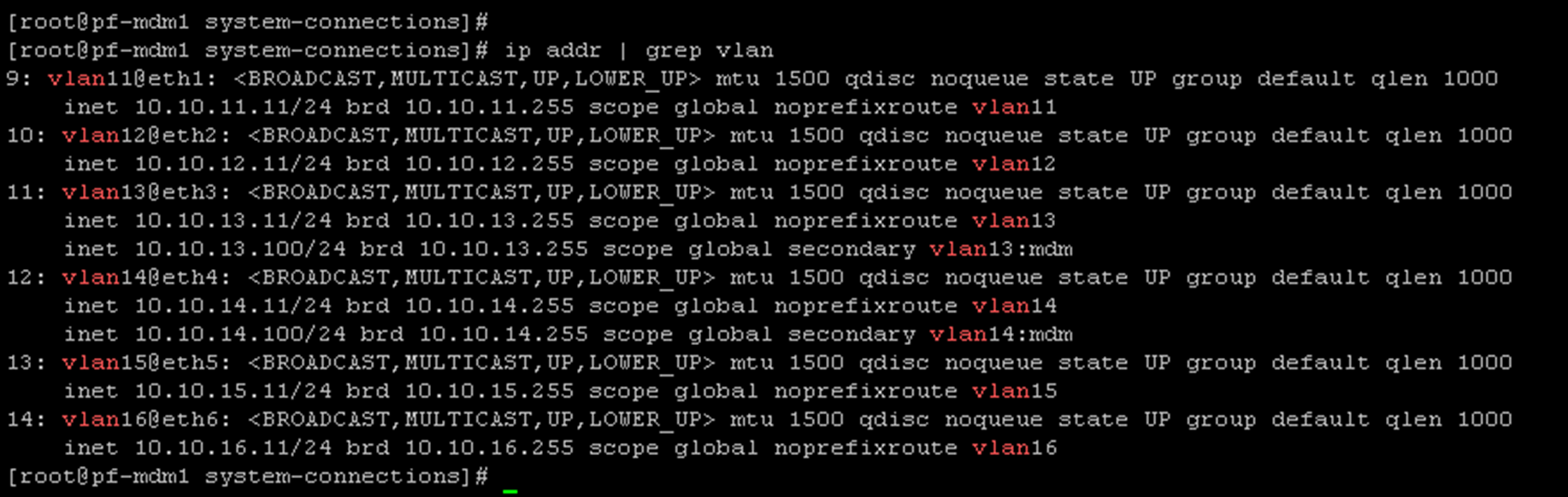
8- In our lab, VLANs 13 and 14 are used by the front-end traffic. This means the Storage Data Client (SDC) will consume the volumes from the Storage Data Server (SDS) using these IPs. Since we already have a default gateway (configured through the management interface), we will configure a Policy-Based Route (PBR) for both front-end VLANs. It will guarantee that both front-end VLANs are available on the network using their default gateway (instead of using the management default gateway) – we are doing it because our SDCs are not on the same front-end network – in a real-world implementation; this step is not necessary:
echo "13 vlan13" >> /etc/iproute2/rt_tables
echo "14 vlan14" >> /etc/iproute2/rt_tables
Edit the “/etc/rc.d/rc.local” file and add the following content:
ip rule add from 10.10.13.0/24 table vlan13
ip route add default via 10.10.13.1 dev vlan13 table vlan13
ip rule add from 10.10.14.0/24 table vlan14
ip route add default via 10.10.14.1 dev vlan14 table vlan14
Add the execute permission to the file and reboot the system:
chmod +x /etc/rc.d/rc.local
reboot
Remember, VLANs 13 and 14 are the VLANs used by the front-end traffic in our lab. Each VLAN is mapped to 10.10.13.0/24 and 10.10.14.0/24, respectively!
The script “/etc/rc.d/rc.local” is executed on each boot, adding the necessary routes under the custom route tables for each VLAN!
Do the same steps on all five nodes!
Install and Configure the PowerFlex Gateway
The gateway is the PowerFlex Installer, the PowerFlex REST API gateway, and the SNMP trap sender. The PowerFlex Gateway can be installed on Linux or Windows. A PowerFlex Gateway installed on Windows can deploy PowerFlex system components on both Linux and Windows-based servers:
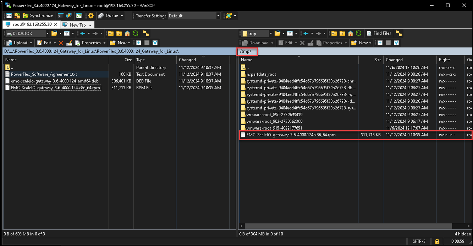
1- Copy the PowerFlex Gateway package from the extracted download file to the server on which you will install the package. The recommended location on the server is the /tmp/ directory;
2- Install the PowerFlex Gateway on the Linux server by running the following command (all on one line) – in this example, we are considering using a CentOS 9 Stream Linux:
# Installing some necessary packages:
dnf update -y
dnf install epel-release -y
dnf install java-1.8.0-openjdk java-1.8.0-openjdk-devel -y
java -version

# Installing the Gateway package. Replacing "<new_GW_admin_password>" by the desired admin password:
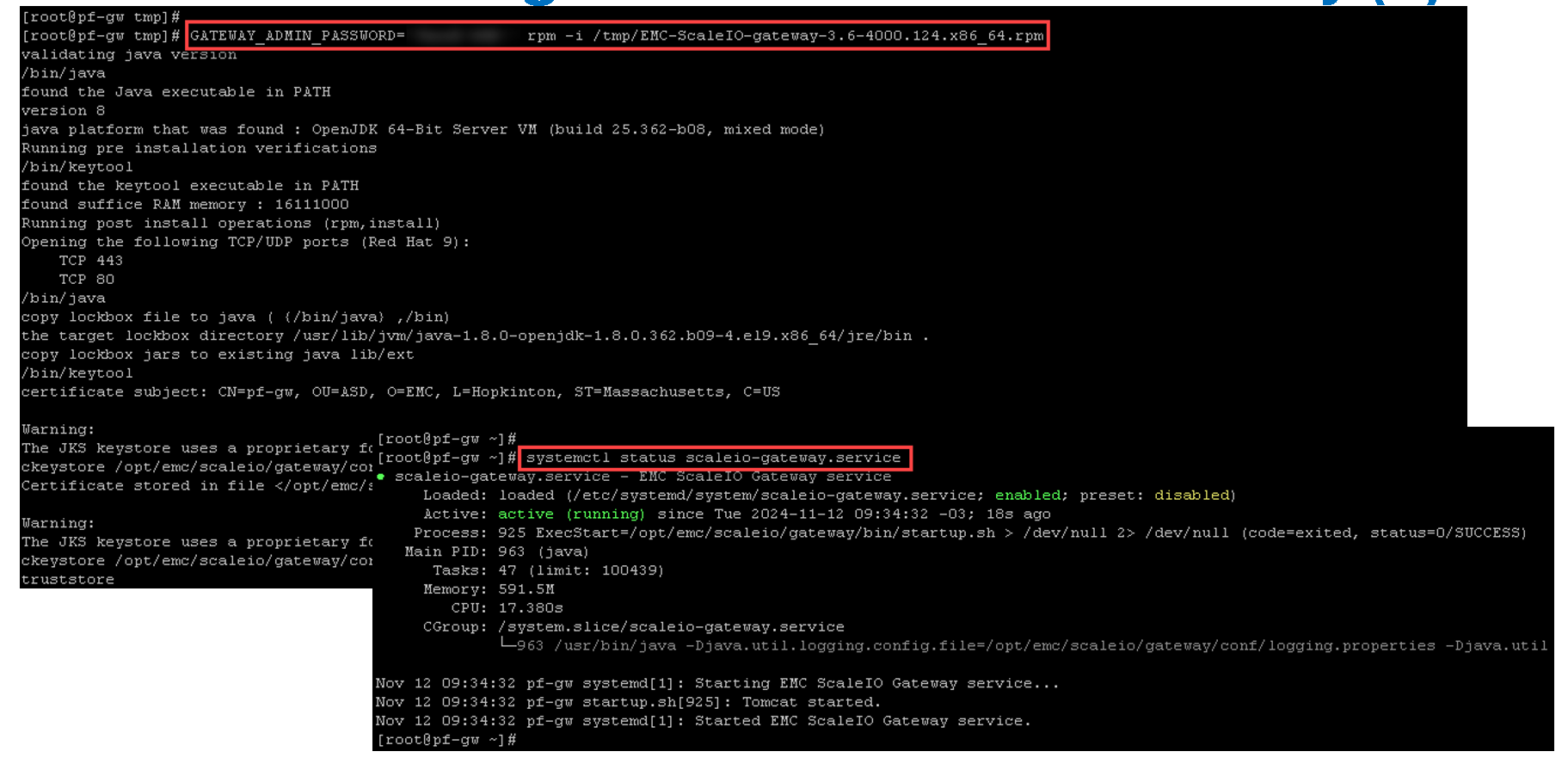
GATEWAY_ADMIN_PASSWORD=<new_GW_admin_password> rpm -i /tmp/EMC-ScaleIO-gateway-3.6-4000.124.x86_64.rpm
Copying the rpm package from the local machine to the PowerFlex Gateway virtual machine:
Installing the rpm package and checking the gateway service status (scaleio-gateway.service):
Afterward, we can access the PowerFlex Gateway:
https://IP_POWERFLEX_GW
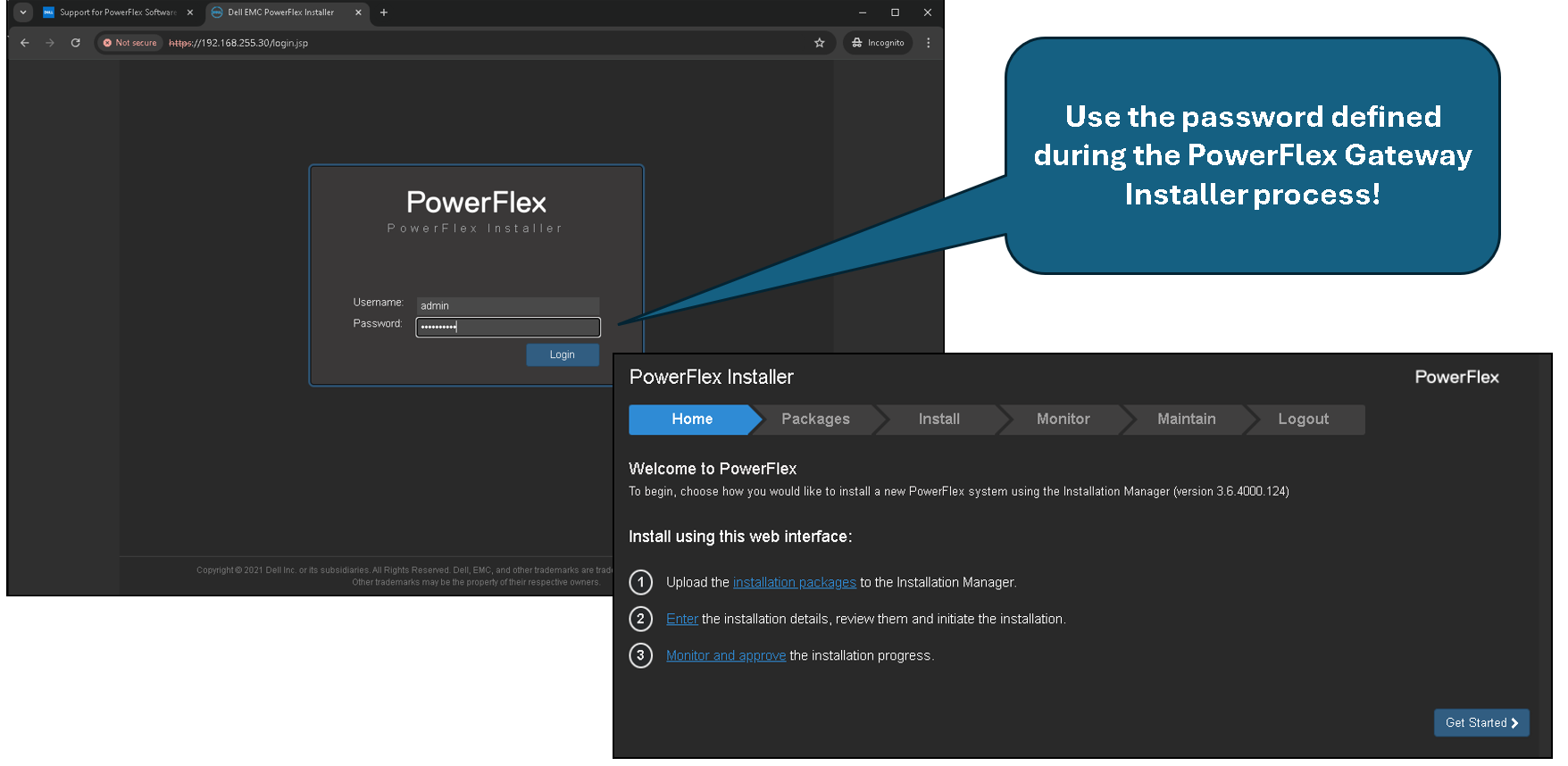
At this point, the PowerFlex Gateway has been deployed successfully!
Deploy the PowerFlex Cluster
As we explained, we are using the PowerFlex 3.6.4 in this lab.
The first step is to download all packages from support.dell.com.
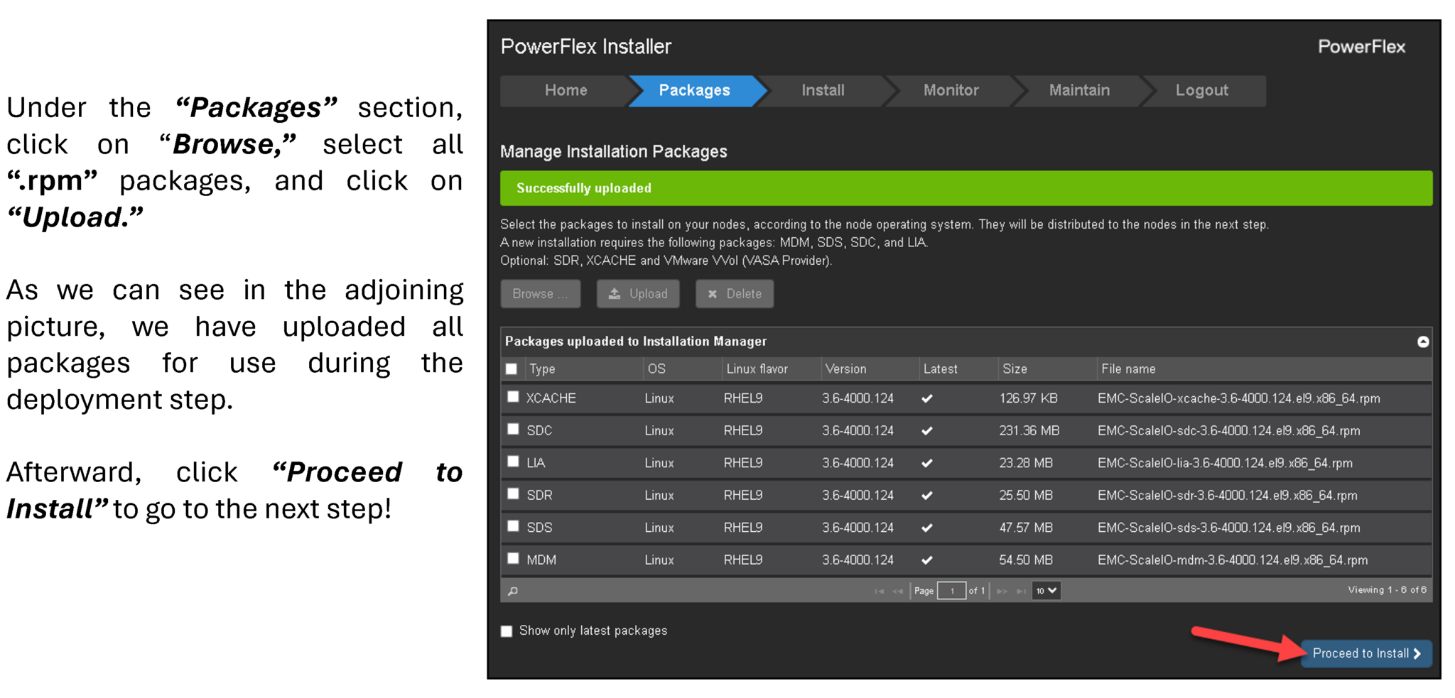
The second step is to access the PowerFlex Gateway interface and upload all installation packages, as we can see in the following figure:
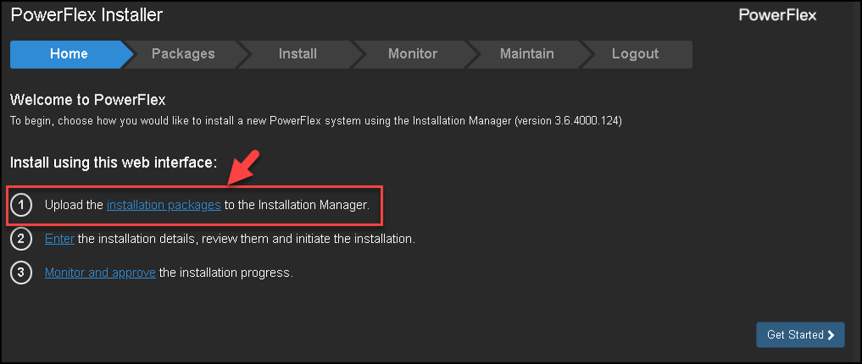
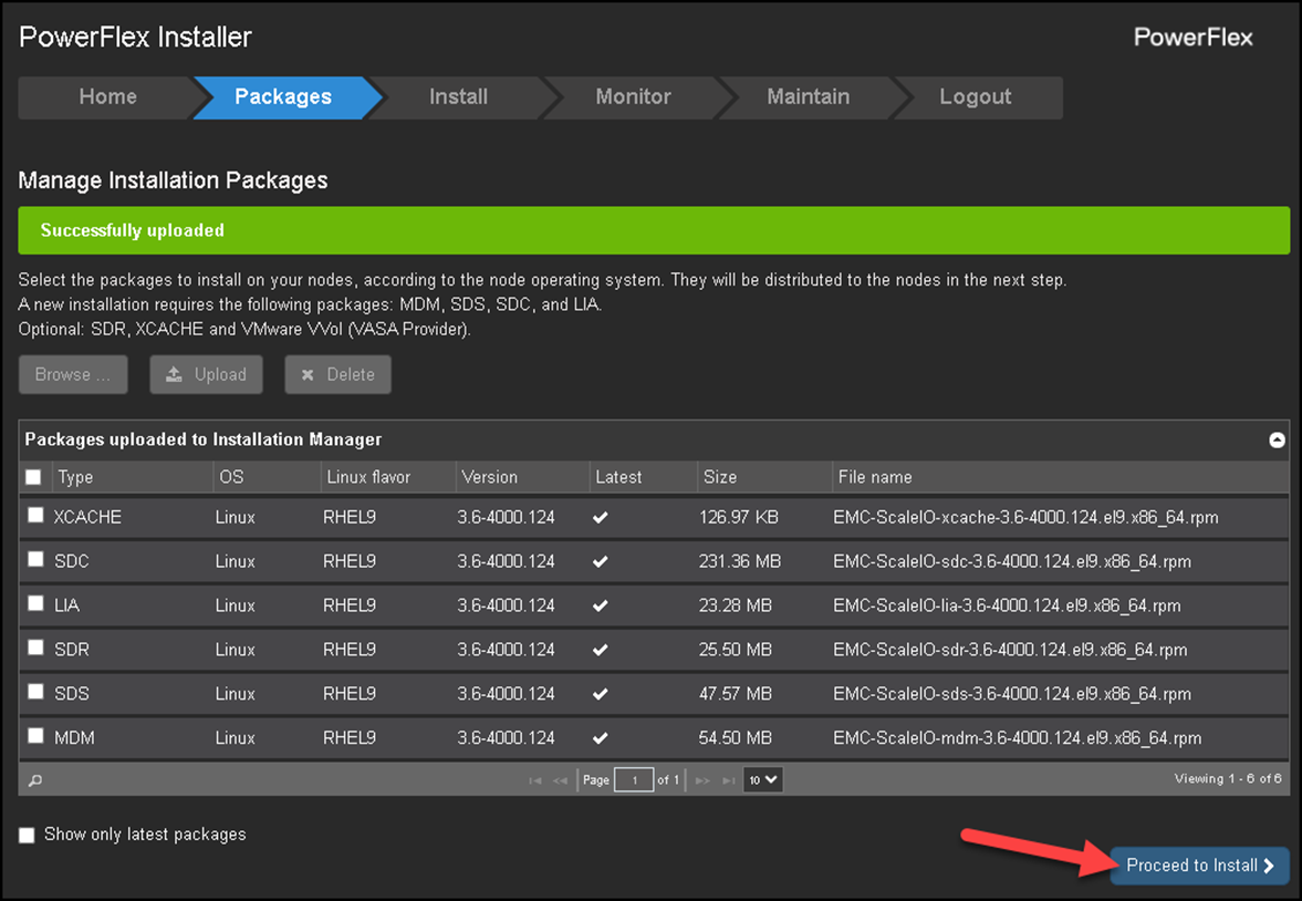
Under the “Packages” section, click on “Browse,” select all “.rpm” packages, and click on “Upload.”
As we can see in the adjoining picture, we have uploaded all packages for use during the deployment step.
Afterward, click “Proceed to Install” to go to the next step:
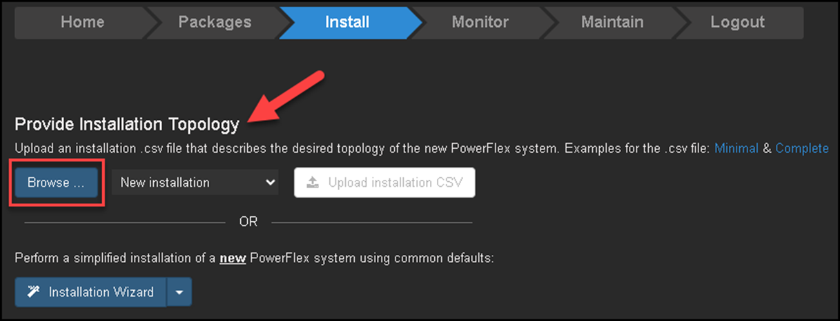
Under the “Install” section, we have both ways to deploy the PowerFlex:
— The first way is to provide an installation topology (CSV) file. This is a custom method to deploy;
— The second way is to use the installation wizard.
We will provide the installation topology file for this deployment.
Access the PowerFlex Gateway:
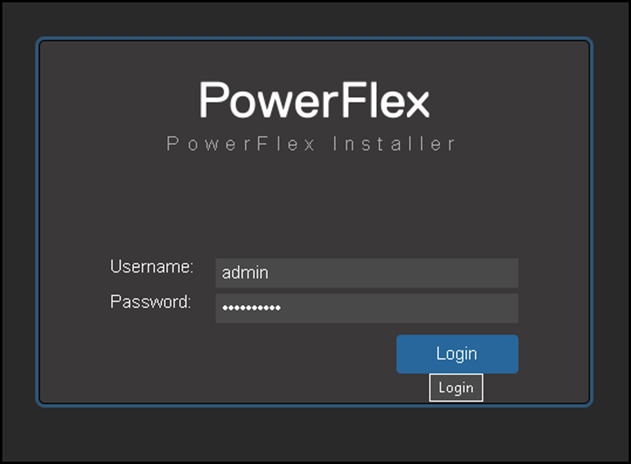
Under Install, click on Browse and select the CSV file:
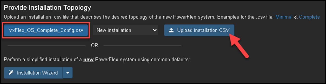
Note: I have shared a copy of the CSV file that I used for this deployment:
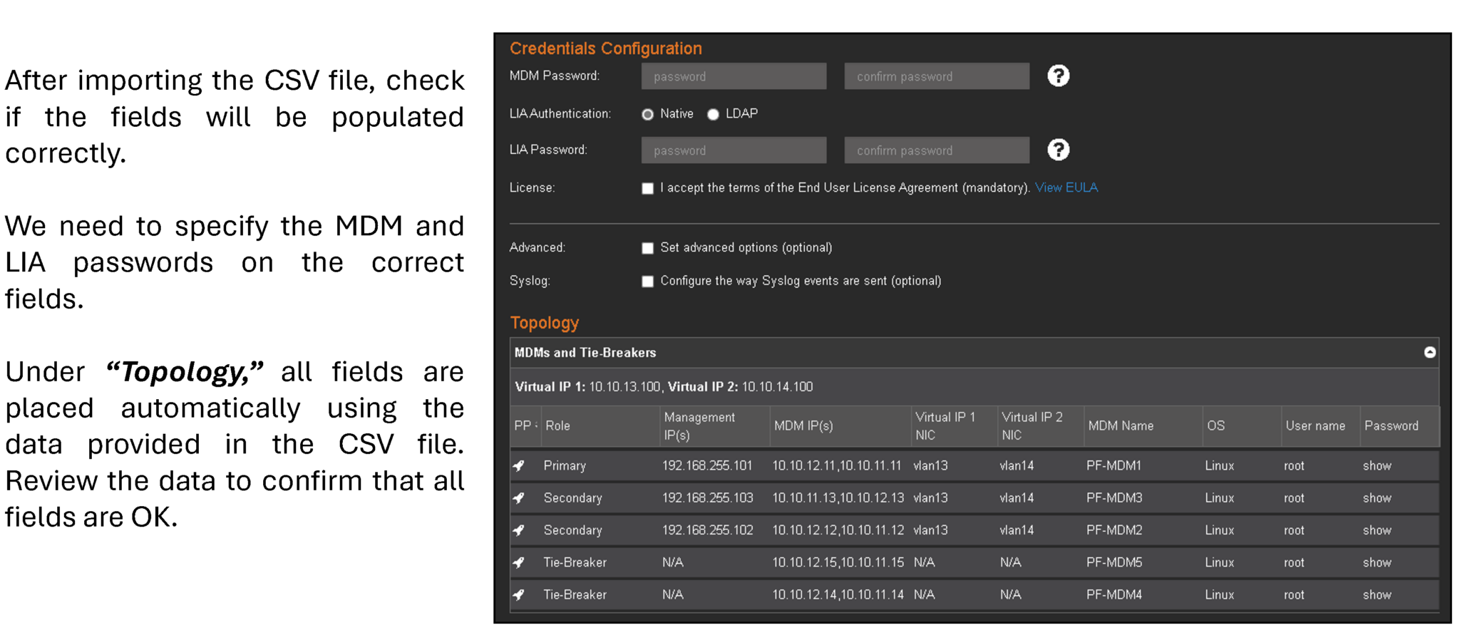
Review all populated details and click on “Start Installation”:
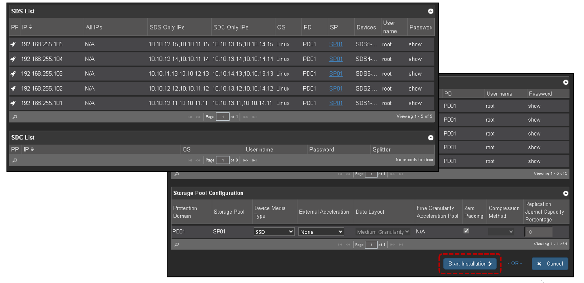
The installation process is a straightforward task. Follow the next steps and wait for the installation to complete!
Afterward, access the primary MDM node and get the cluster details:
scli --login --username admin

scli --query_cluster

Example:

[root@pf-mdm2 ~]# scli --query_cluster
Cluster:
    Name: PF5NodeCluster, Mode: 5_node, State: Normal, Active: 5/5, Replicas: 3/3
    SDC refresh with MDM IP addresses: disabled
    Virtual IP Addresses: 10.10.13.100, 10.10.14.100
Master MDM:
    Name: PF-MDM2, ID: 0x0cbf1ddc1448a902
        IP Addresses: 10.10.12.12, 10.10.11.12, Management IP Addresses: 192.168.255.102, Port: 9011, Virtual IP interfaces: vlan13, vlan14
        Status: Normal, Version: 3.6.4000
Slave MDMs:
    Name: PF-MDM1, ID: 0x05313fc85a6b1400
        IP Addresses: 10.10.12.11, 10.10.11.11, Management IP Addresses: 192.168.255.101, Port: 9011, Virtual IP interfaces: vlan13, vlan14
        Status: Normal, Version: 3.6.4000
    Name: PF-MDM3, ID: 0x554d3f32355b8901
        IP Addresses: 10.10.11.13, 10.10.12.13, Management IP Addresses: 192.168.255.103, Port: 9011, Virtual IP interfaces: vlan13, vlan14
        Status: Normal, Version: 3.6.4000
Tie-Breakers:
    Name: PF-MDM4, ID: 0x2bd3d2110b863b04
        IP Addresses: 10.10.12.14, 10.10.11.14, Port: 9011
        Status: Normal, Version: 3.6.4000
    Name: PF-MDM5, ID: 0x4ea9ca512f887103
        IP Addresses: 10.10.12.15, 10.10.11.15, Port: 9011
Status: Normal, Version: 3.6.4000Note: A healthy five-node result should show a normal state, all expected MDM members active, three repository replicas, and the configured virtual IP addresses. The exact field names can vary by PowerFlex release. Use the output to confirm the actual cluster rather than copying a screenshot as proof of health.
Example of the important values to verify:
Cluster:
    Mode: 5_node
    State: Normal
    Active: 5/5
    Replicas: 3/3
    Virtual IP Addresses: 10.10.13.100, 10.10.14.100
Install and Configure the PowerFlex Presentation Server
The Presentation Server is an essential component that serves as the User Interface (UI) and API layer, facilitating management and monitoring of the PowerFlex environment.
It hosts the PowerFlex UI and APIs, allowing administrators to manage resources, configure settings, and view performance metrics.
As a bridge between users and backend services, it ensures a streamlined and centralized point for control and data visualization across storage, compute, and network components in a PowerFlex deployment.
1- Copying the rpm package (mgmt-server) from the local machine to the server:
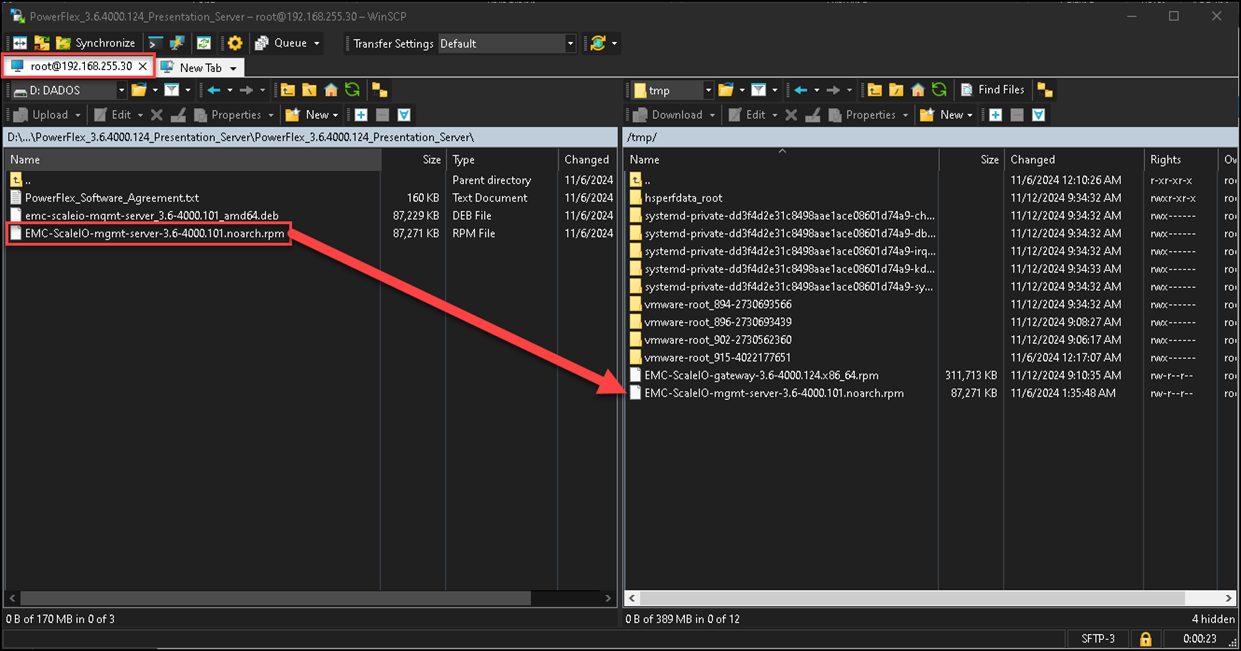
2- Installing the JAVA package:
yum install -y java-11-openjdk3- Installing the rpm package and checking the service status:
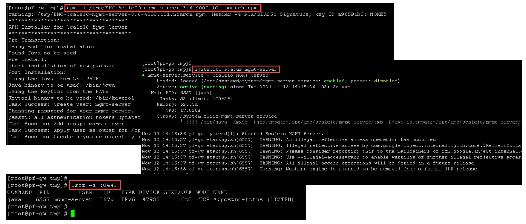
4- To access the PowerFlex Presentation Server, use the following address:
https://IP_PRESENTATION_SERVER:8443
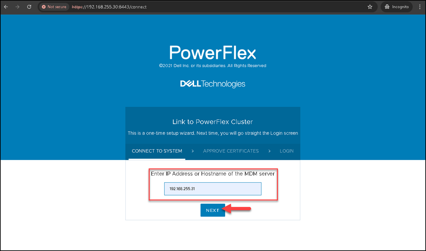
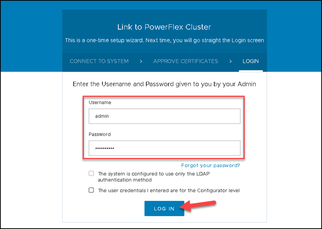
To manage an MDM cluster through the Presentation Server, we must specify the MDM Primary IP and click on NEXT, as we can see in the following example:
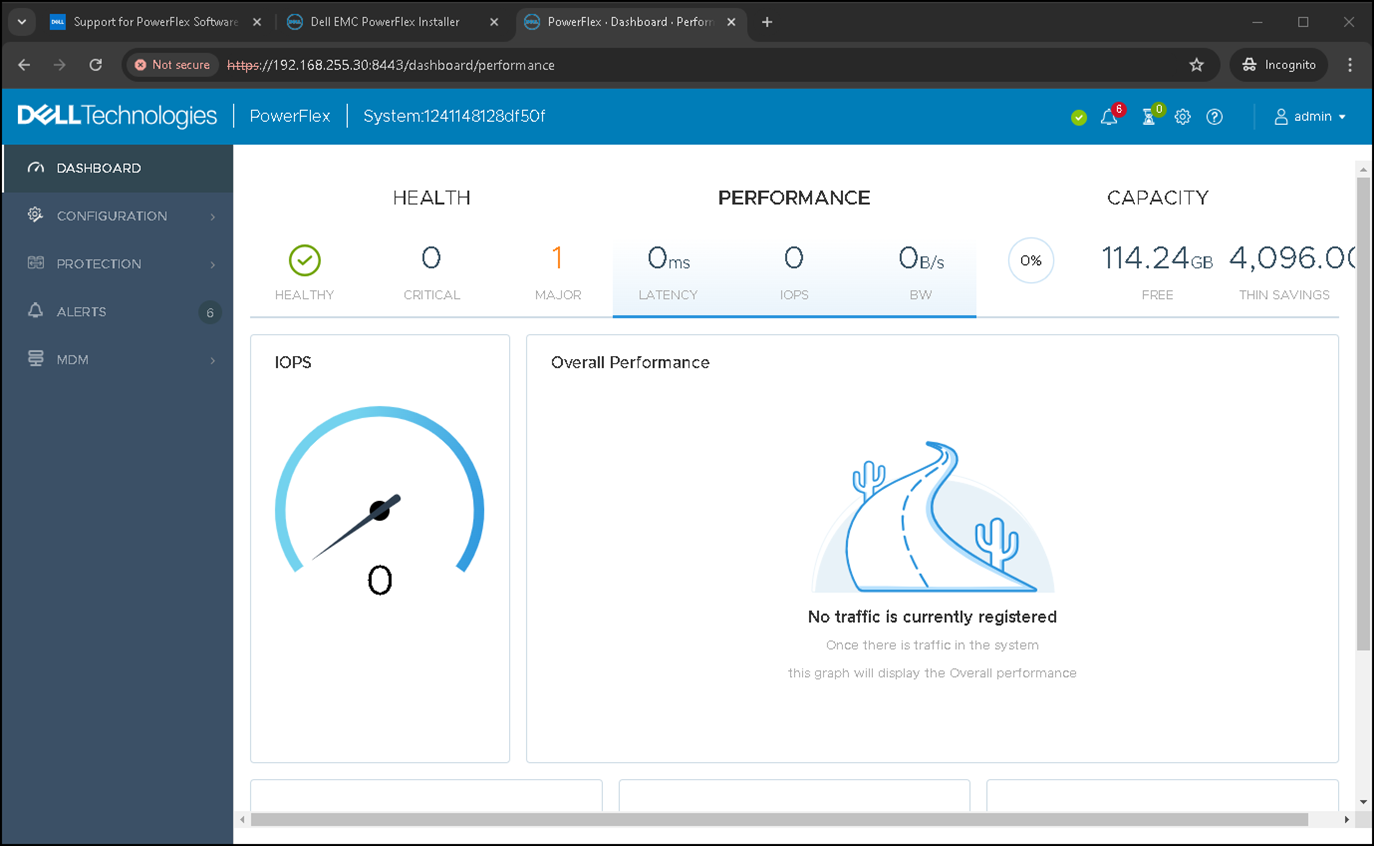
This is the Presentation Server Dashboard. We will explore more details further:
Deploy a Windows-Based Storage Data Client (SDC)
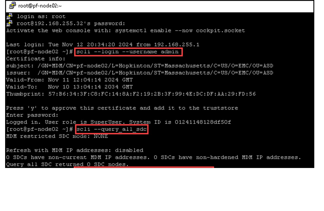
As we can see, we do not have any SDC connected to our PowerFlex cluster:
We will install the SDC and LIA packages in a Windows server system. Copy both packages to the Windows system, open the command line (cmd), and run the following commands to install each package:
# Installing the SDC package - change the MDM IP 192.168.255.40 to your MDM IP or Virtual IP
msiexec /i C:\Users\Administrator\Desktop\EMC-ScaleIO-sdc-3.6-4000.124.msi MDM_IP=192.168.255.40 /norestart

# Installing the LIA package - type the LIA password on the variable "TOKEN":
msiexec /i C:\Users\Administrator\Desktop\EMC-ScaleIO-lia-3.6-4000.124.msi TOKEN=‘lia_password’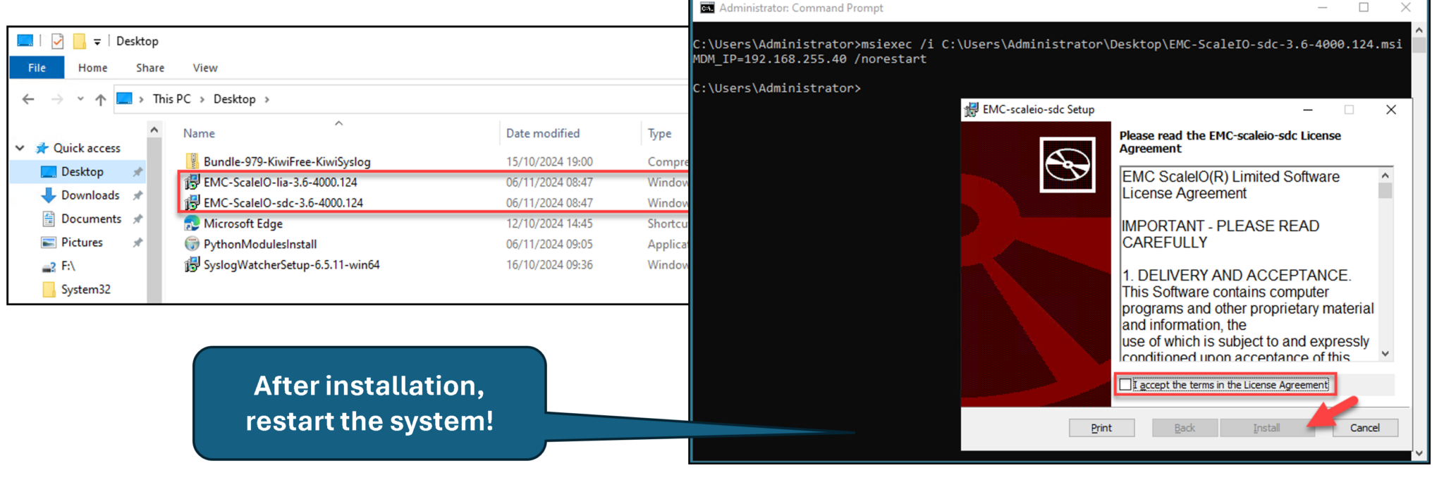
Generating a CHAP password for SDC to MDM authentication:
scli --generate_sdc_password --sdc_ip 192.168.255.3 --reason "chap setup"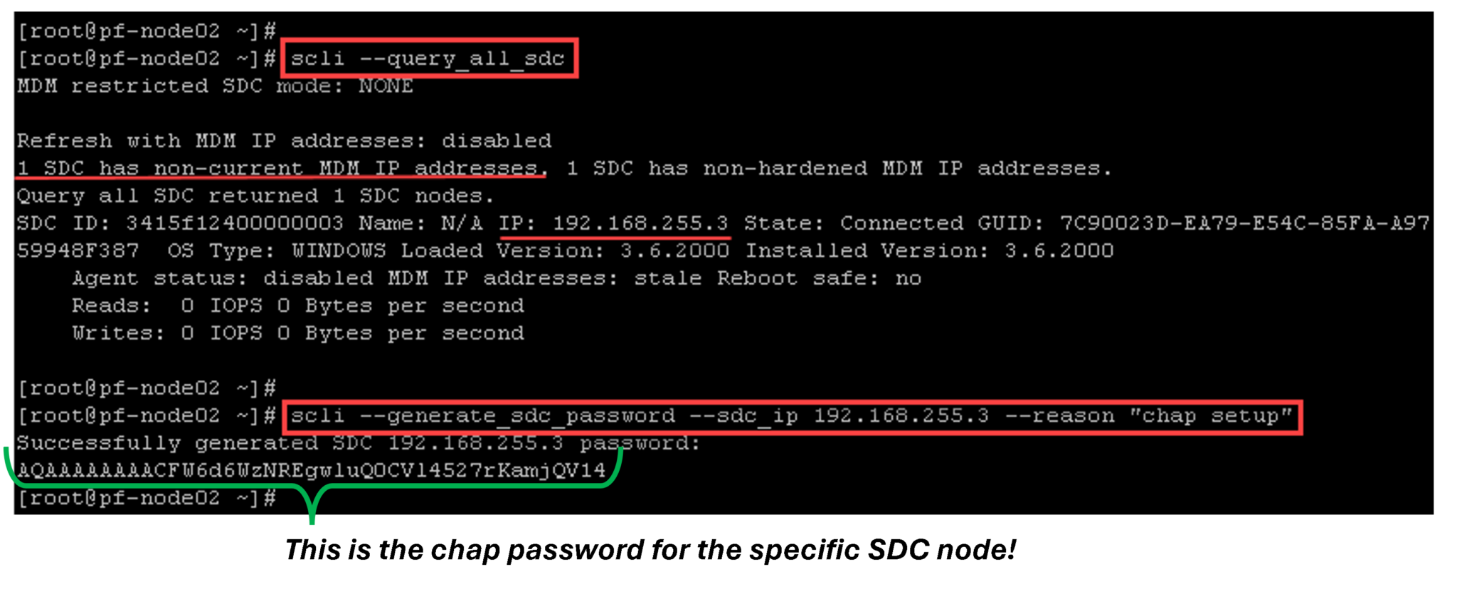
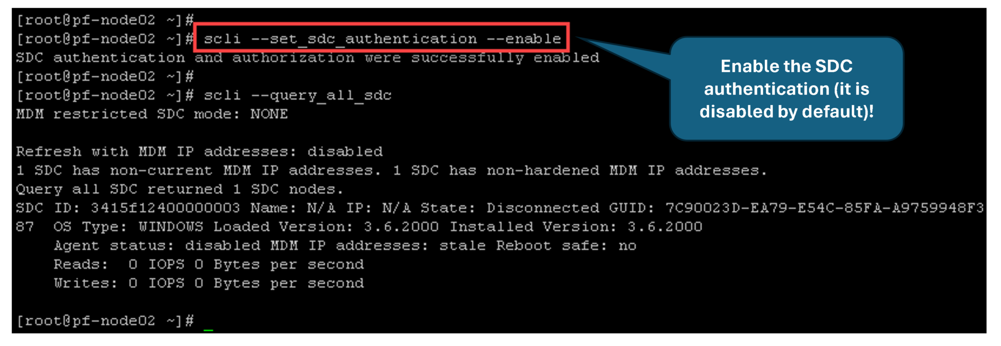
Setting the SDC password up from the Windows SDC. Open the cmd with admin rights and execute the following commands:
"C:\Program Files\EMC\scaleio\sdc\bin\drv_cfg.exe" --query_mdms

"C:\Program Files\EMC\scaleio\sdc\bin\drv_cfg.exe" --set_mdm_password --ip 192.168.255.40 --port 6611 --password AQAAAAAAAACFW6d6WzNREgwluQ0CVl4527rKamjQV14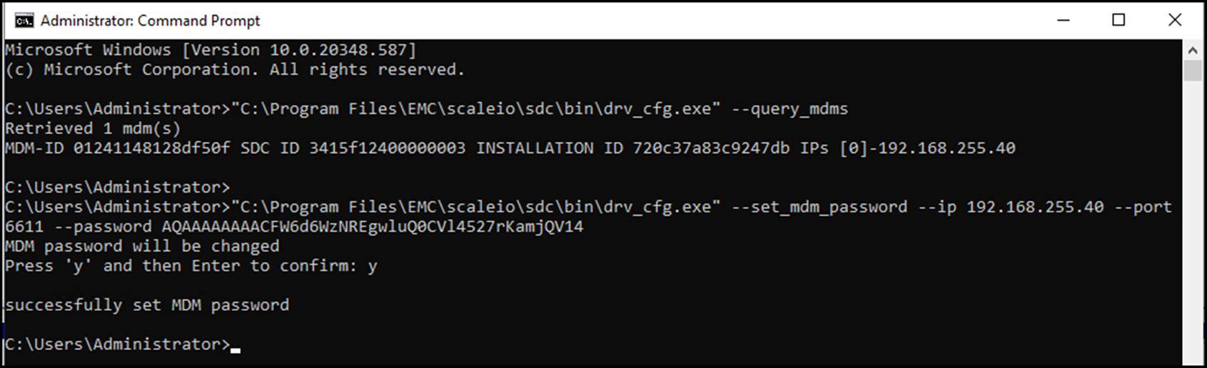
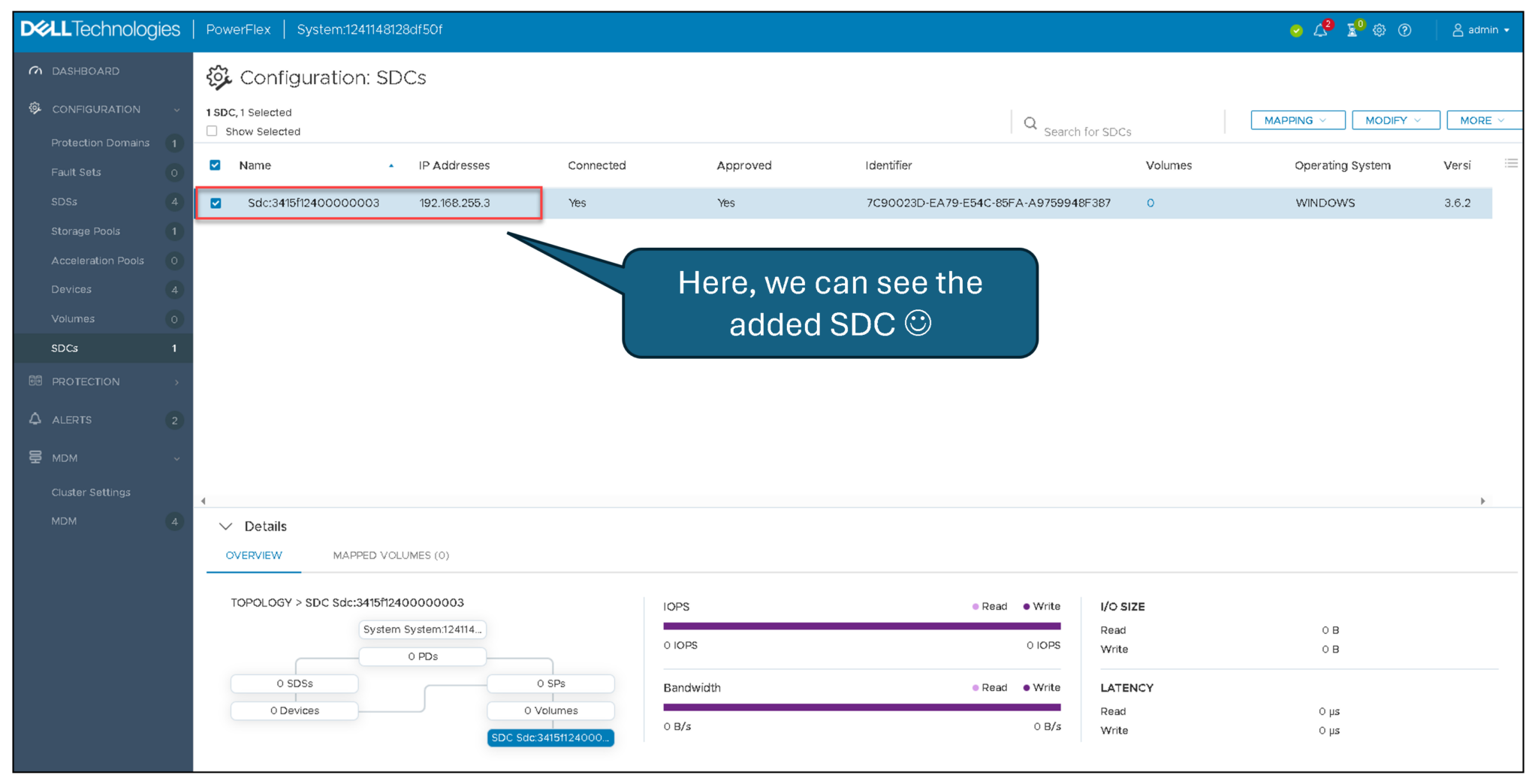
On the Presentation Server, under SDCs, we can see the Windows SDC:
Creating a Volume and Mapping it to a Windows-Based SDC
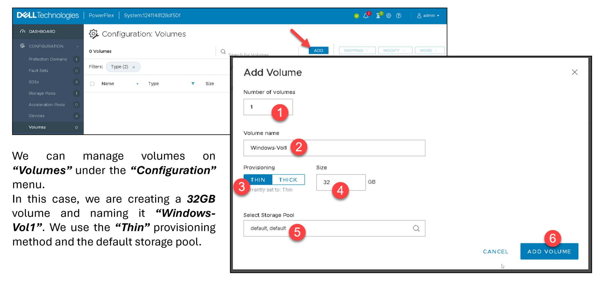
On the Presentation Server, access the Volumes menu under Configuration and follow the steps below:
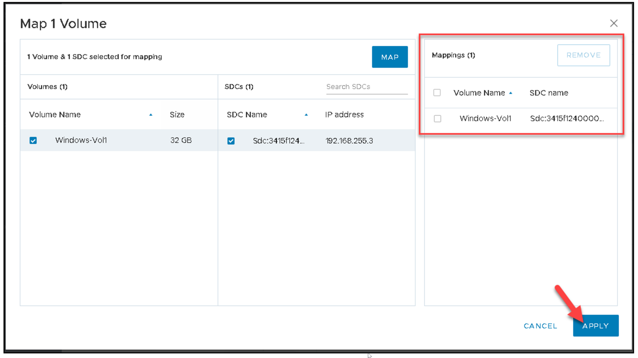
After adding the volume, we must map it to SDC:
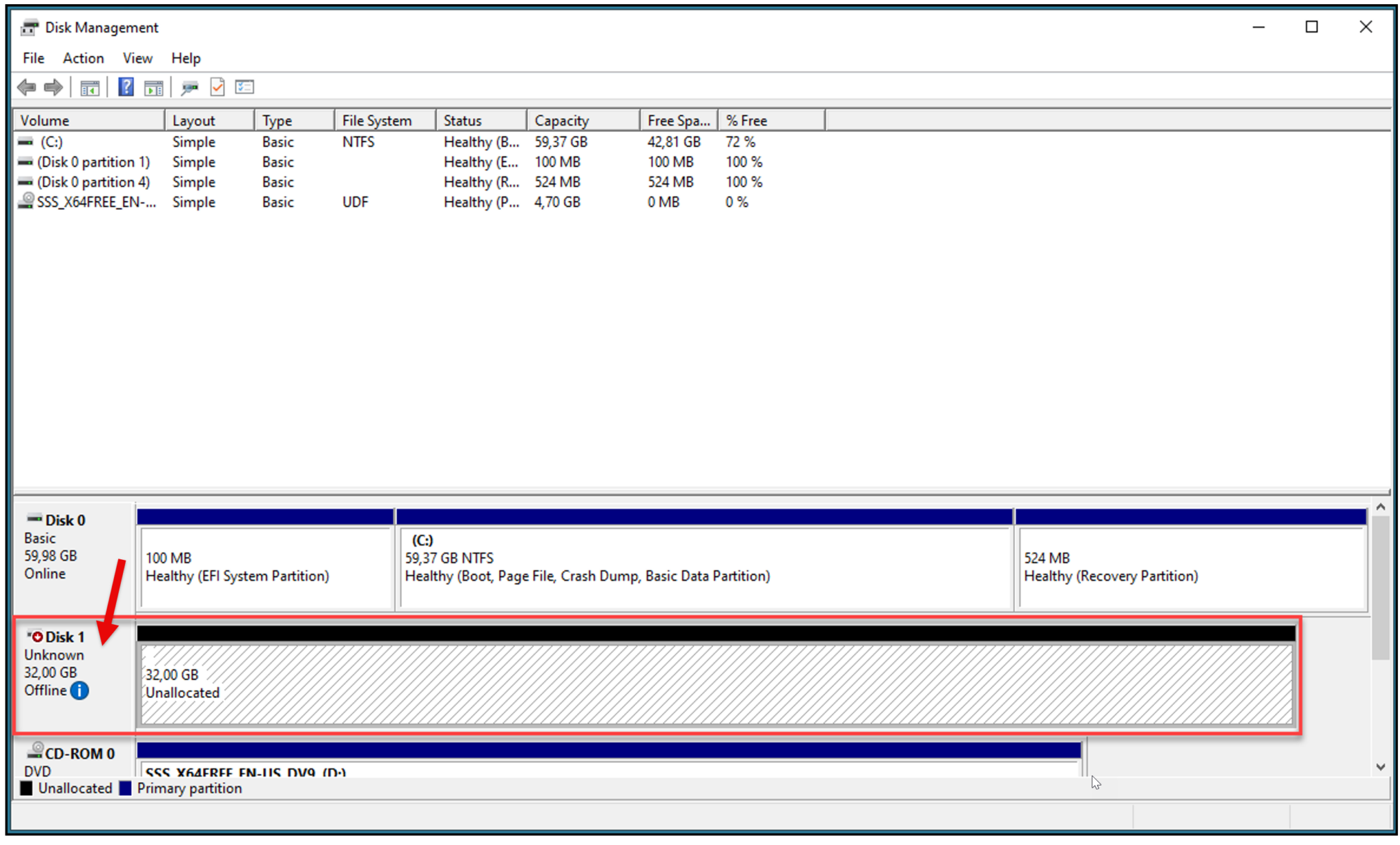
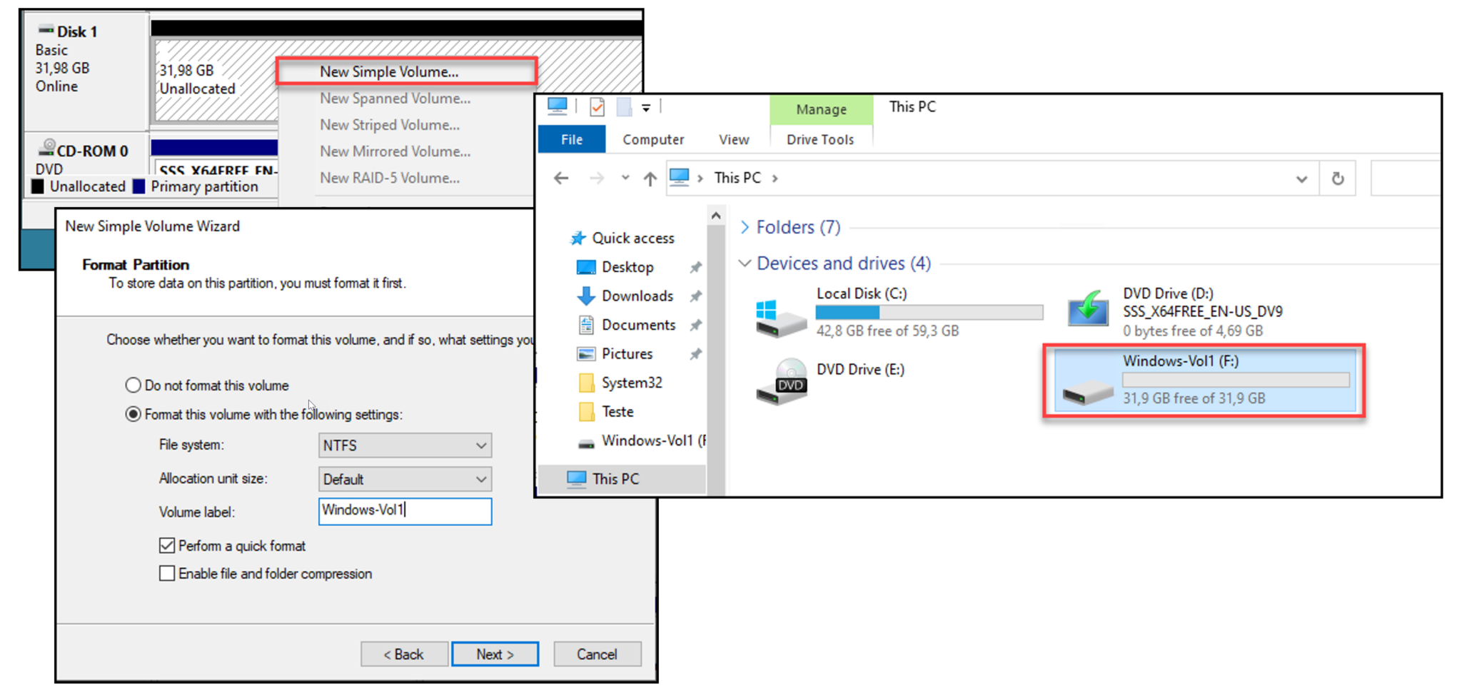
Go to the Windows Server and open the Disk Management. A new disk should appear:
Initialize the new disk and create a simple volume (Next –> Next –> Finish):
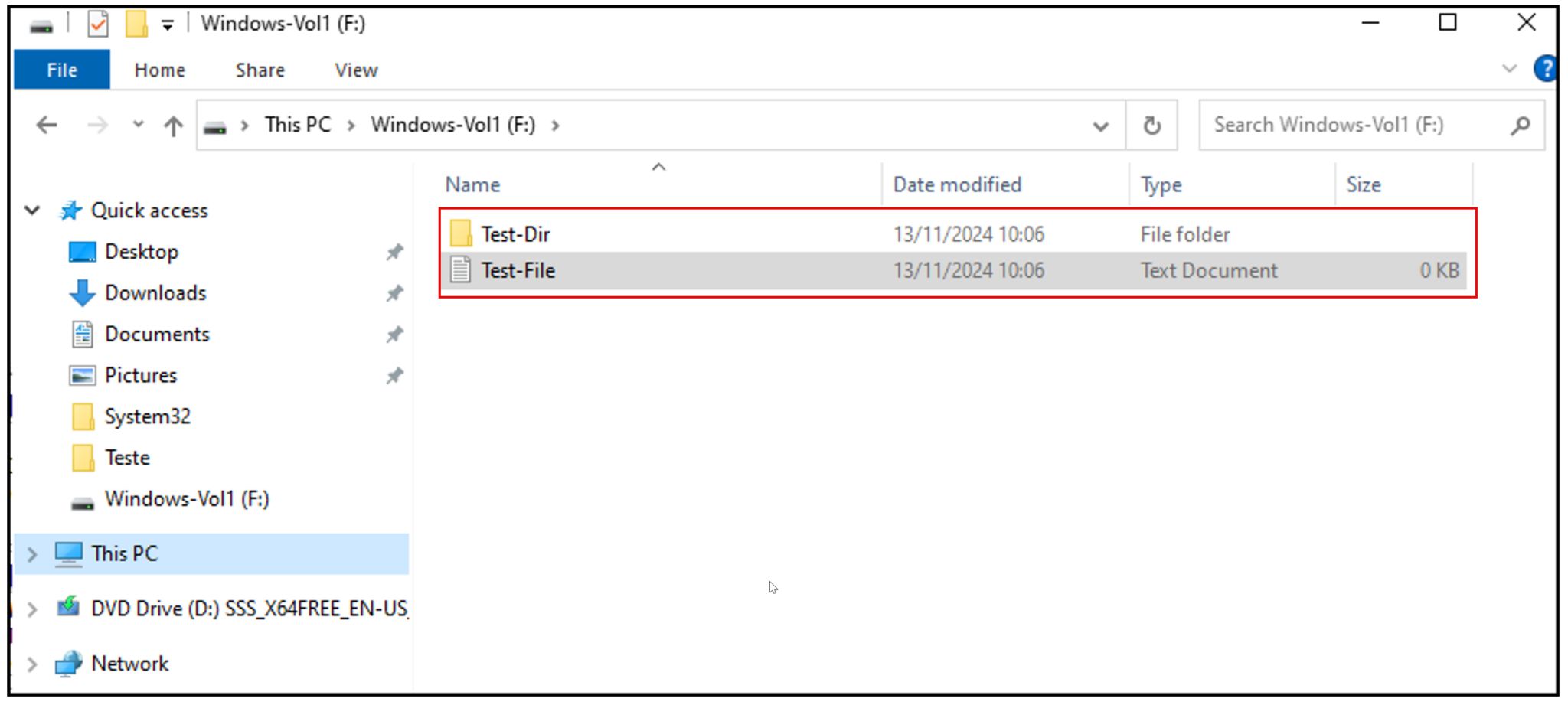
As we can see, we can create files and directories under the new volume:
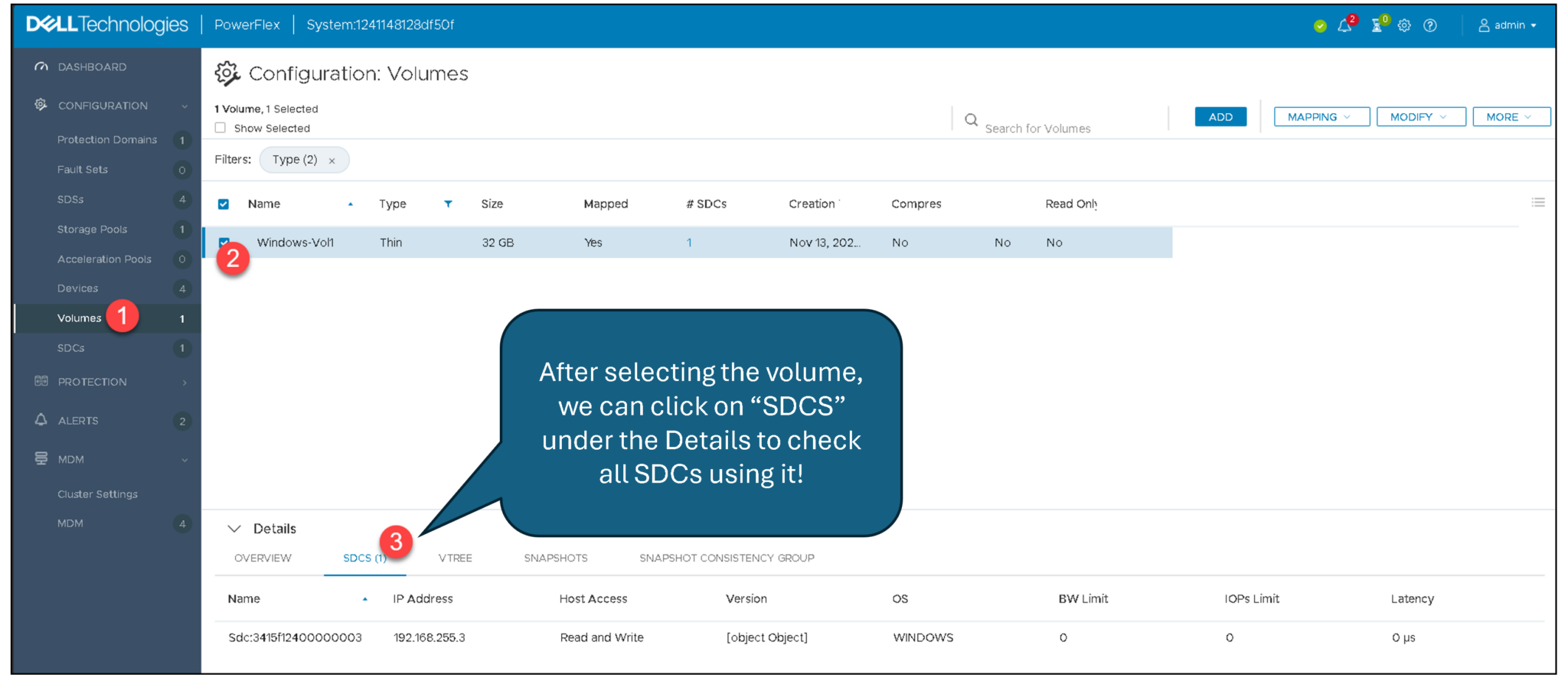
We can select the volume on the Presentation Server and click on the “SDCs” tab. We can see all SDCs that are accessing the volume:
Deploy an ESXi-Based Storage Data Client (SDC)
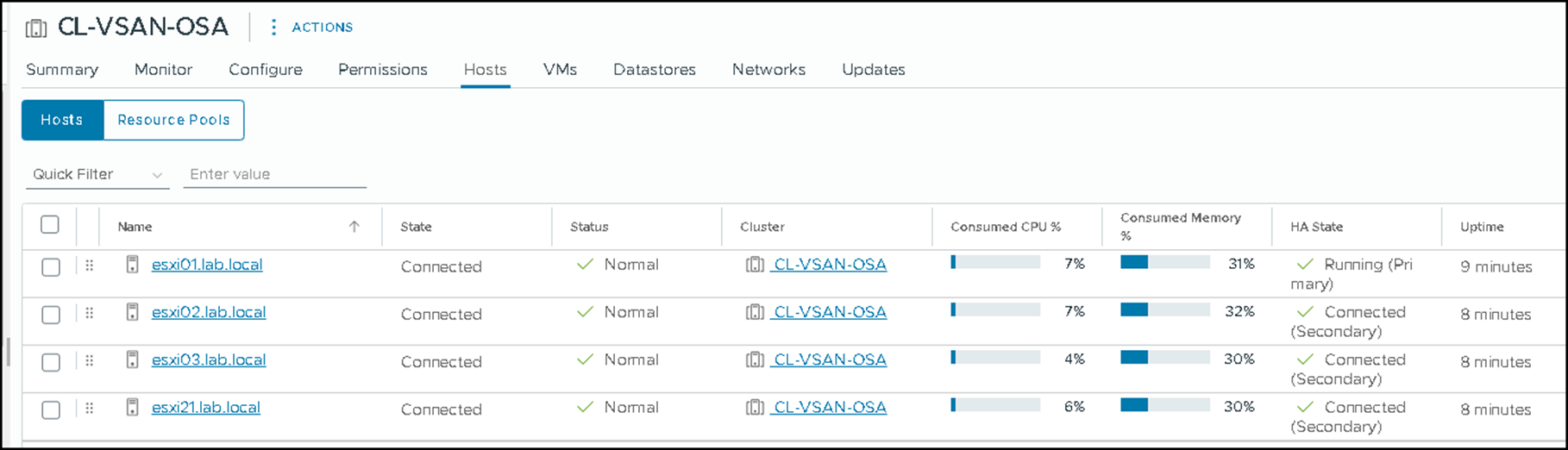
In this case, we have a vSAN cluster with four ESXi hosts. We will manually install the SDC software (VIB) on each ESXi host. Afterward, we will configure the SDC software to “connect” to the MDM cluster:
The first step is to copy the SDC installation package to each ESXi host. For instance, we are copying the SDC package “sdc-3.6.2000.112-esx7.x.zip” to the /tmp directory on each ESXi host. We are using the package for vSphere 7 (choose the package based on your vSphere environment version).
Installing the SDC package on the ESXi host:
esxcli software vib install -d /tmp/sdc-3.6.2000.112-esx7.x.zip
After the SDC package (VIB) installation, we must reboot the ESXi host (put it in maintenance mode and reboot it!). There is a required step to finish the VIB installation!
Access the MDM cluster, disable (temporarily) the SDC authentication, and generate an ESXi password for further authentication:
scli --set_sdc_authentication --disable
Query all SDC and grab the ESXi SDC ID – we will use this information to generate the SDC password:
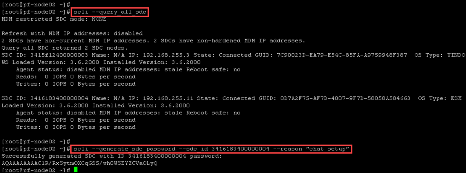
Enable SDC authentication:
scli --set_sdc_authentication --enable
Configure the SDC client to connect to the MDM cluster on the ESXi host (access it by SSH).
To get the IoctlIniGuidStr:
esxcli system module parameters list -m scini | grep IoctlConnect the ESXi to the MDM cluster:
esxcli system module parameters set -m scini -p "IoctlIniGuidStr=0d7a2f75-af7d-4007-9f7d-58058a584663 IoctlMdmIPStr=192.168.255.40 IoctlMdmPasswordStr=192.168.255.40-AQAAAAAAAAClR/RxSytmOXCqGSS/wh0WSEYZCVaOLyQ“Afterward, we must reboot the ESXi host to apply the configuration!
Create a Volume and Map it to an ESXi-Based SDC
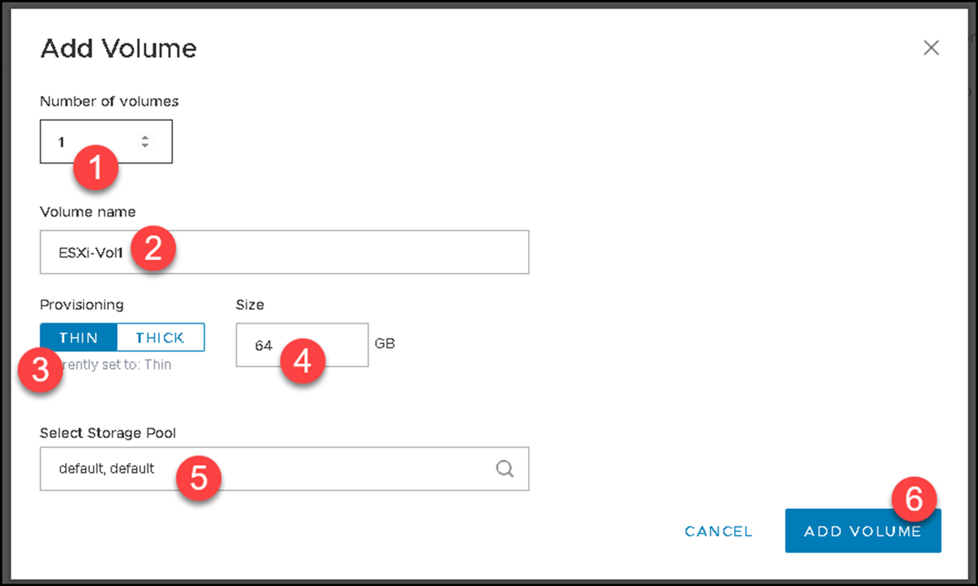
Create a volume named “ESXi-Vol1” with 64GB:
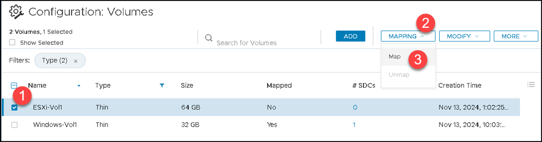
Map the volume to the ESXi host:

Under Storage Adapters on the ESXi host, click on “RESCAN ADAPTER.”
The “vmhba65” adapter is used to map the PowerFlex volumes:
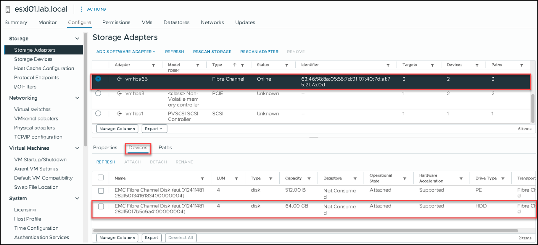
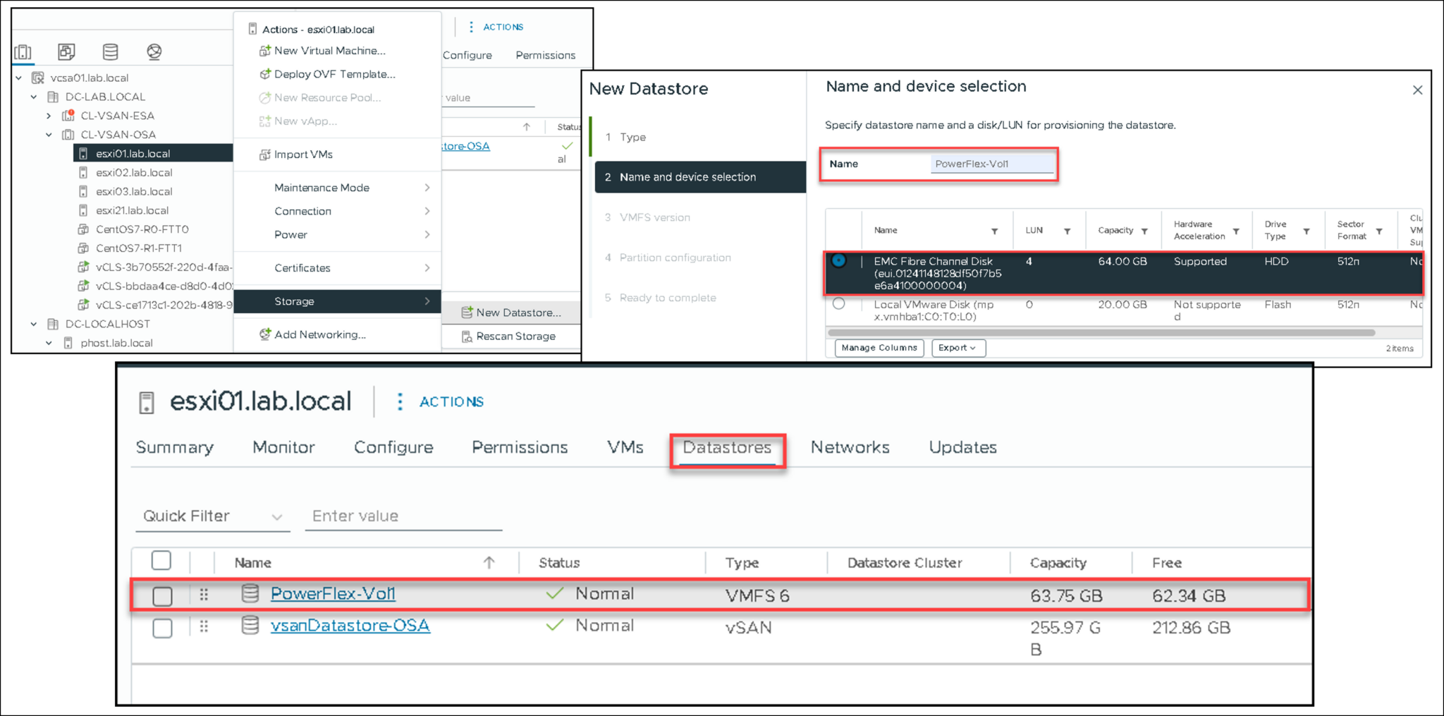
Since the volume has been mapped to the ESXi host, we can create a Datastore:
Closing Thoughts
This lab demonstrates how PowerFlex turns local disks on several nodes into a shared software-defined storage system. The most important lessons are not the individual installer screens but the relationships between the MDM control plane, SDS storage contributors, SDC consumers, network separation, and MDM quorum.
Once the cluster reports a normal state and clients can create and use mapped volumes, the environment is ready for controlled experiments with storage pools, protection domains, snapshots, rebalance operations, and replication.
For production deployments, replace the nested topology with Dell-validated hardware, supported software combinations, redundant network paths, documented recovery procedures, and a design reviewed against the current PowerFlex release documentation.
External References
- Dell — Deploy PowerFlex 3.6.x Official deployment guide for PowerFlex 3.6.x, including Gateway installation, topology-based deployment, MDM cluster creation, and component installation workflows.
- Dell — PowerFlex 3.6.4 Release Notes Release-specific information about PowerFlex 3.6.4 software packages, operating-system support, and compatibility considerations.
- Dell — Install PowerFlex Gateway on Linux Official instructions for installing the PowerFlex Gateway on a Linux server and preparing it for PowerFlex deployment operations.
- Dell — PowerFlex MDM Cluster Explains MDM cluster roles, primary and secondary managers, tiebreakers, repository replicas, and three-node and five-node configurations.
- Dell — Install MDM Packages for a Five-Node Cluster Release-specific deployment procedure for installing the MDM packages and creating a five-node PowerFlex MDM cluster.
- Dell — Install SDC on ESXi Servers Official overview of installing the PowerFlex SDC on ESXi hosts through command-line tools or the vSphere PowerFlex plug-in.
- Dell — Install and Connect an ESXi-Based SDC Using ESXCLI Detailed PowerFlex 3.6.x instructions for installing the ESXi SDC and connecting it to the MDM cluster with ESXCLI.
- Dell — Install SDC on a Windows-Based Server Official PowerFlex 3.6.x instructions for installing a Windows SDC and connecting it to an existing PowerFlex system.
- Red Hat — Consistent Network Interface Device Naming Official Red Hat guidance on predictable interface names and custom naming with udev or systemd link files.
- Red Hat — Policy-Based Routing Official NetworkManager guidance for source-based routing, custom routing tables, and routing rules.
- VyOS — Official Documentation Official VyOS documentation for installation, interface configuration, VLANs, routing, and other router functions used in a lab topology.
