
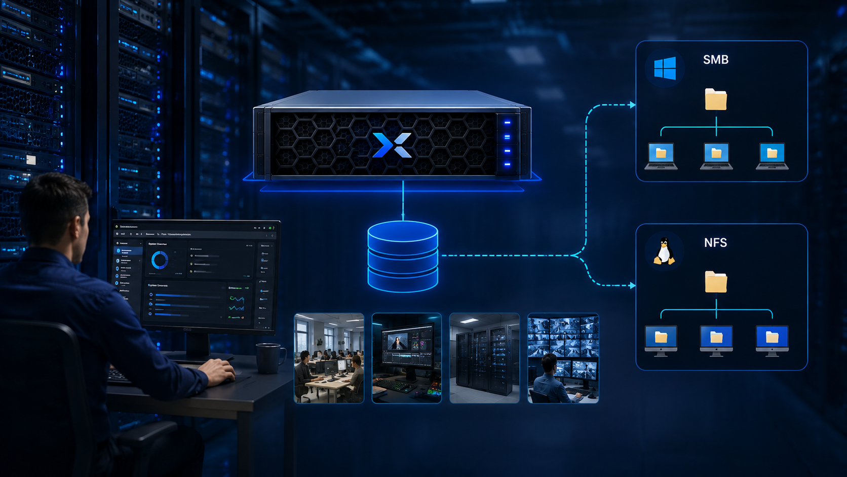
PowerFlex File Services extends Dell PowerFlex beyond block storage by providing file access through protocols such as SMB and NFS. In PowerFlex Manager, the workflow starts with preparing the File Nodes and networks, then creating a NAS Server and a file system before publishing SMB shares or NFS exports.
This walkthrough demonstrates the workflow in a nested lab running PowerFlex 4.5.2 with two virtual File Nodes. It covers resource discovery, template preparation, resource-group deployment, NAS Server and file-system creation, and basic SMB and NFS client access. The lab is for learning and is not a production design or a statement that virtual File Nodes are a Dell-supported deployment configuration. Check the Dell documentation and support matrix for the hardware and software combination before planning a supported environment.
If you are new to the platform, first read Getting Started with Dell PowerFlex: Architecture and Key Components for an overview of the main PowerFlex components and deployment models.
How PowerFlex File Services Is Organized
PowerFlex File Services runs on PowerFlex File Nodes. A NAS Server provides the file-service endpoint and is configured for SMB, NFS, or both, depending on the intended clients and deployment.
A file system provides the storage namespace; SMB shares and NFS exports make directories in that file system available to clients. Although Dell documentation also describes FTP and SFTP capabilities at the broader File Services level, this walkthrough demonstrates SMB shares and NFS exports, not FTP/SFTP access.
Deploying the PowerFlex File Services
This is a nested, virtualized lab created to demonstrate the PowerFlex Manager workflow. Dell’s PowerFlex 4.5.x guide describes the supported File Services node configurations and hardware platforms; therefore, do not infer from this lab that deploying File Nodes as general-purpose VMs is a supported production configuration.
Validate the exact platform against Dell’s current release documentation and support matrix before using it outside a lab
For context on the block cluster used in this lab, see Deploying a New PowerFlex Cluster, which walks through a PowerFlex 4.5.2 software-cluster deployment with PowerFlex Manager. The article covers block-cluster deployment; this guide focuses on the separate File Services workflow.
Discover Resources
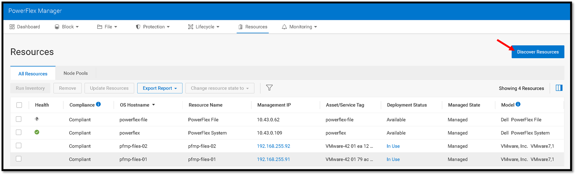
The first step is discovering both File Nodes as a resource in the PowerFlex Cluster. Go to the Resources menu –> Discover Resources:
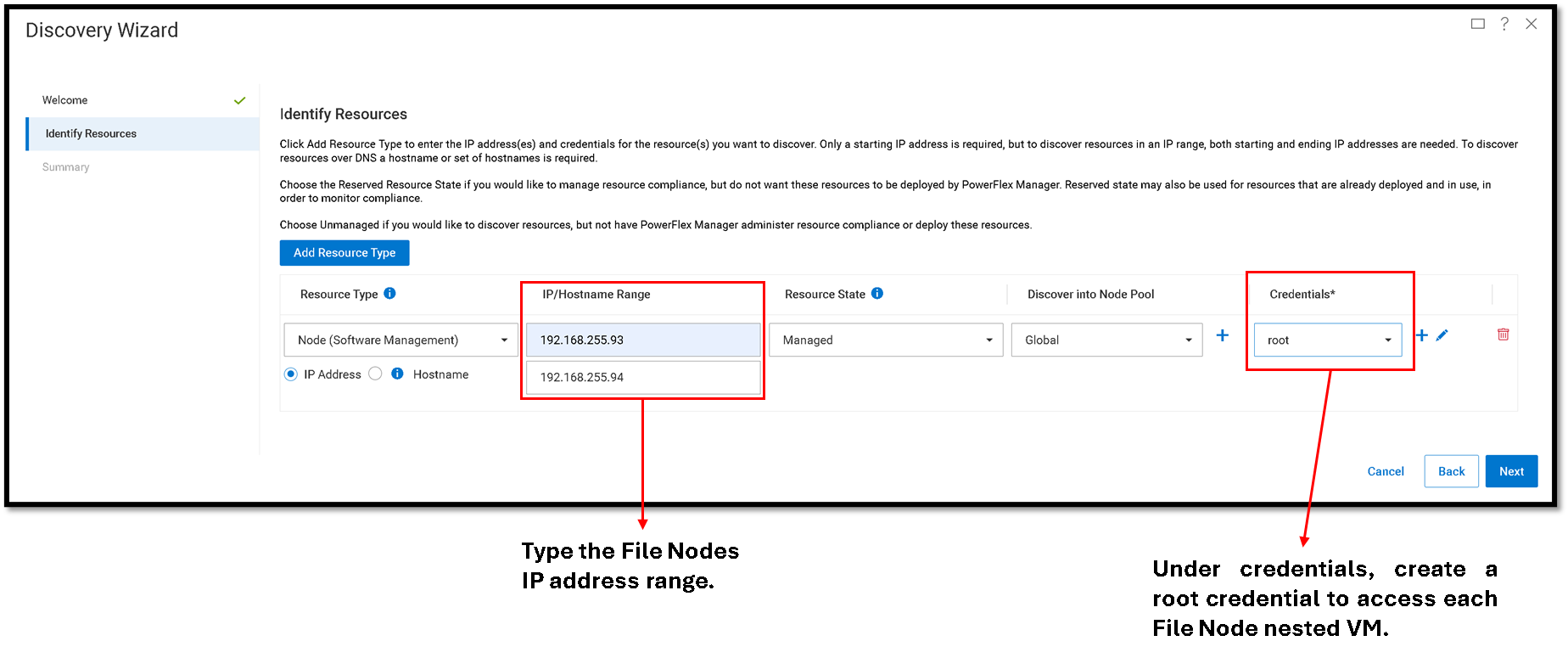
In the “Identity Resources,” we need to specify the resource type and fill all necessary fields, as shown in the following picture.
Since we are not using a physical server, the resource type must be “Node (Software Management)”:
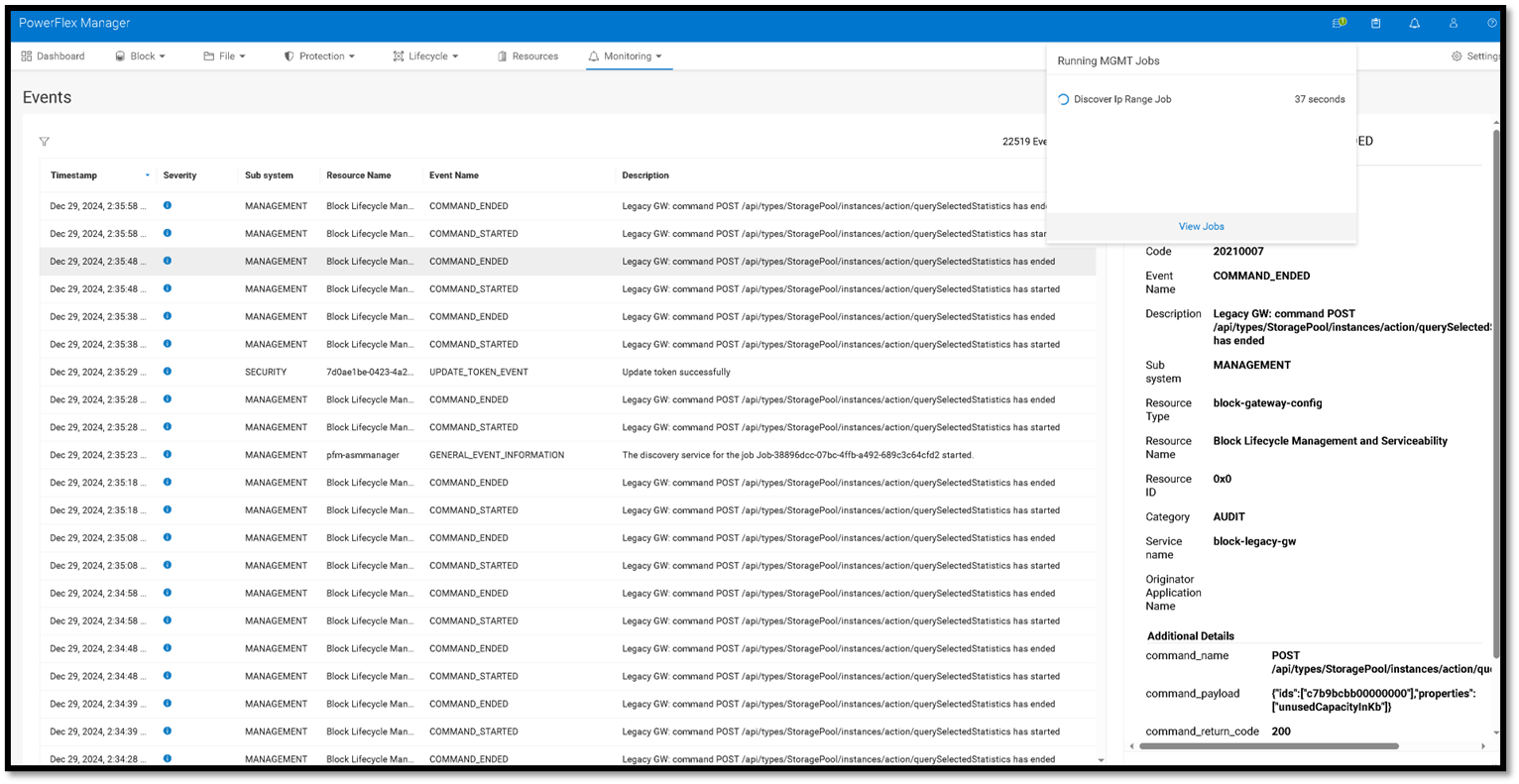
A mgmt job will be created and can be monitored under the “Events” menu:
After some time, we can see events showing that both resources were added successfully:
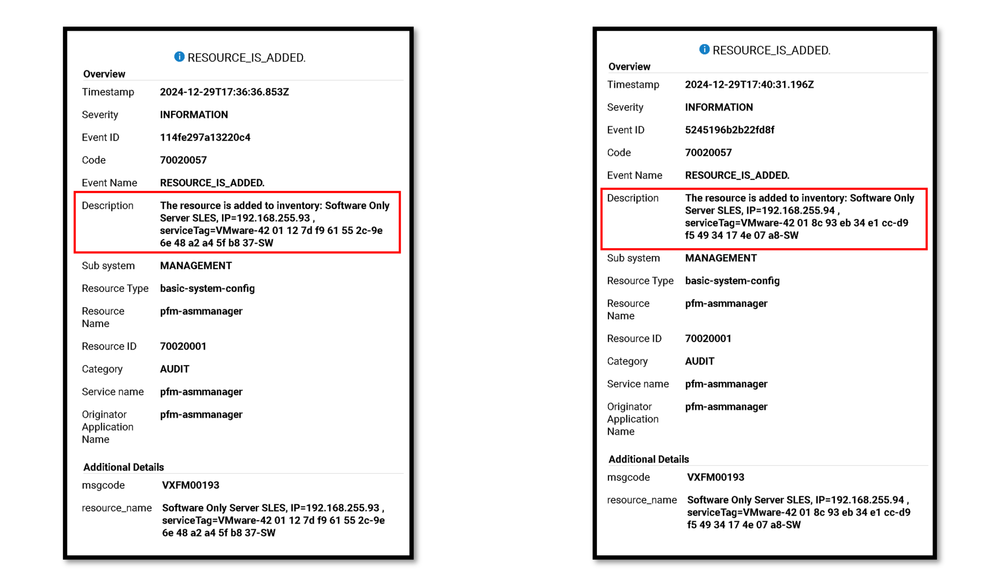
We could see both File Nodes under the Resources menu if the discover resource process was executed successfully. Look at the “Deployment Status” column. “Not in Use” means that the resource is not being used but is available in a resource group:

Create a PowerFlex File Template
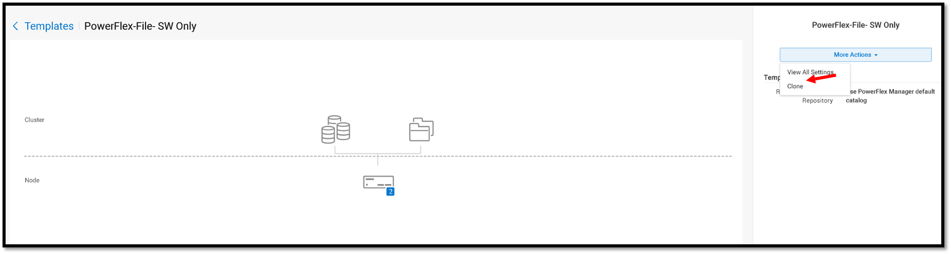
Afterward, we must create a Template to deploy the PowerFlex File Services. Under the Lifecycle menu, select Templates. Click on the Sample Templates tab. In this tab, we can see all sample templates. Click on “PowerFlex-File- SW Only” –> More Actions –> Clone.
We will create a template clone from this sample:
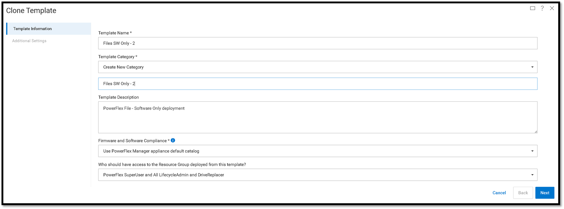
Type the template name and template category, and click on Next to continue:
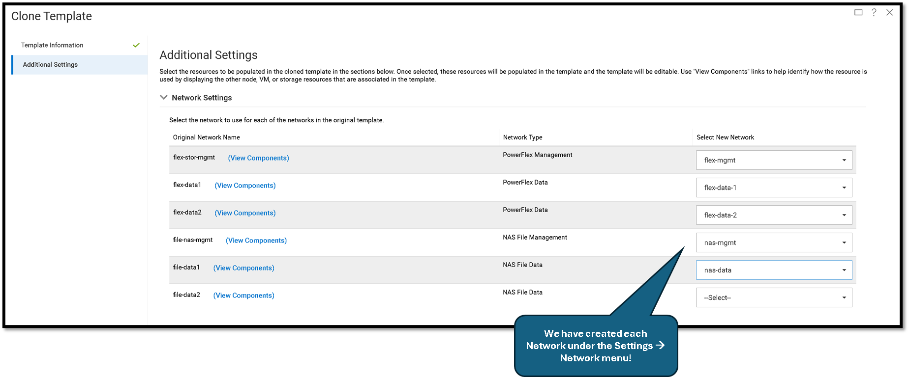
Under “Network Settings,” we must select each network to use on the new template.
Note: We must define the Networks before creating the template. Go to the Settings –> Networks to determine the Networks.
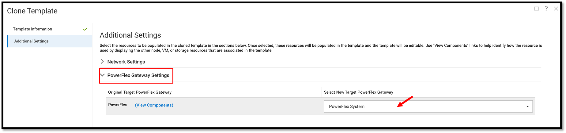
Under “PowerFlex Gateway Settings” we need to select the PowerFlex System:
Under the “Node Pool Settings,” we can maintain the default configuration (Global) and click on Finish to create the template:
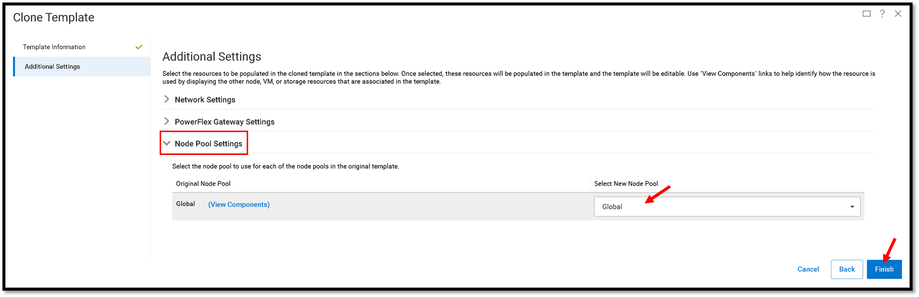
When using a “custom node pool,” select this pool from the “Original Node Pool” option. A Node Pool is a logical container that groups one or more nodes that can be used to create resource pools.
Click on Finish to conclude the template creation!
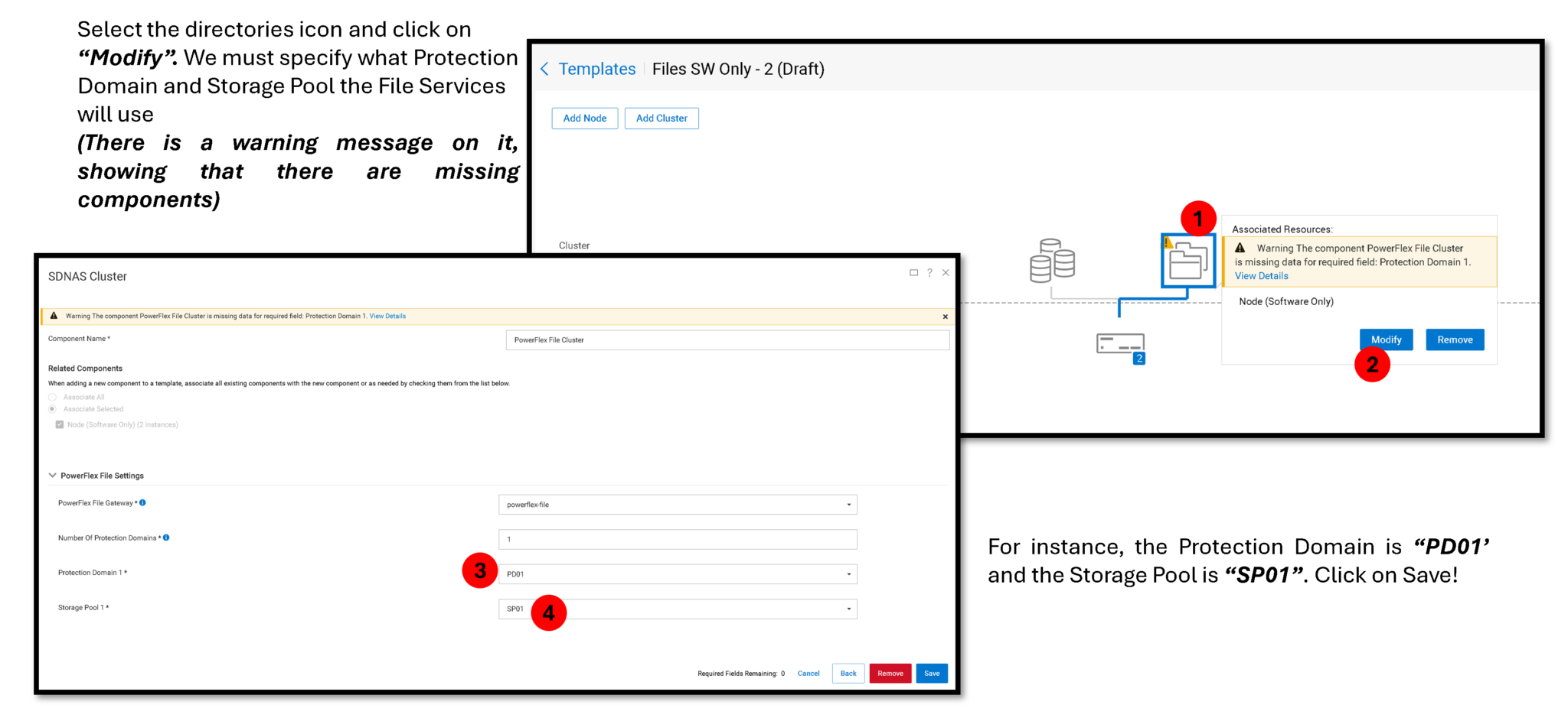
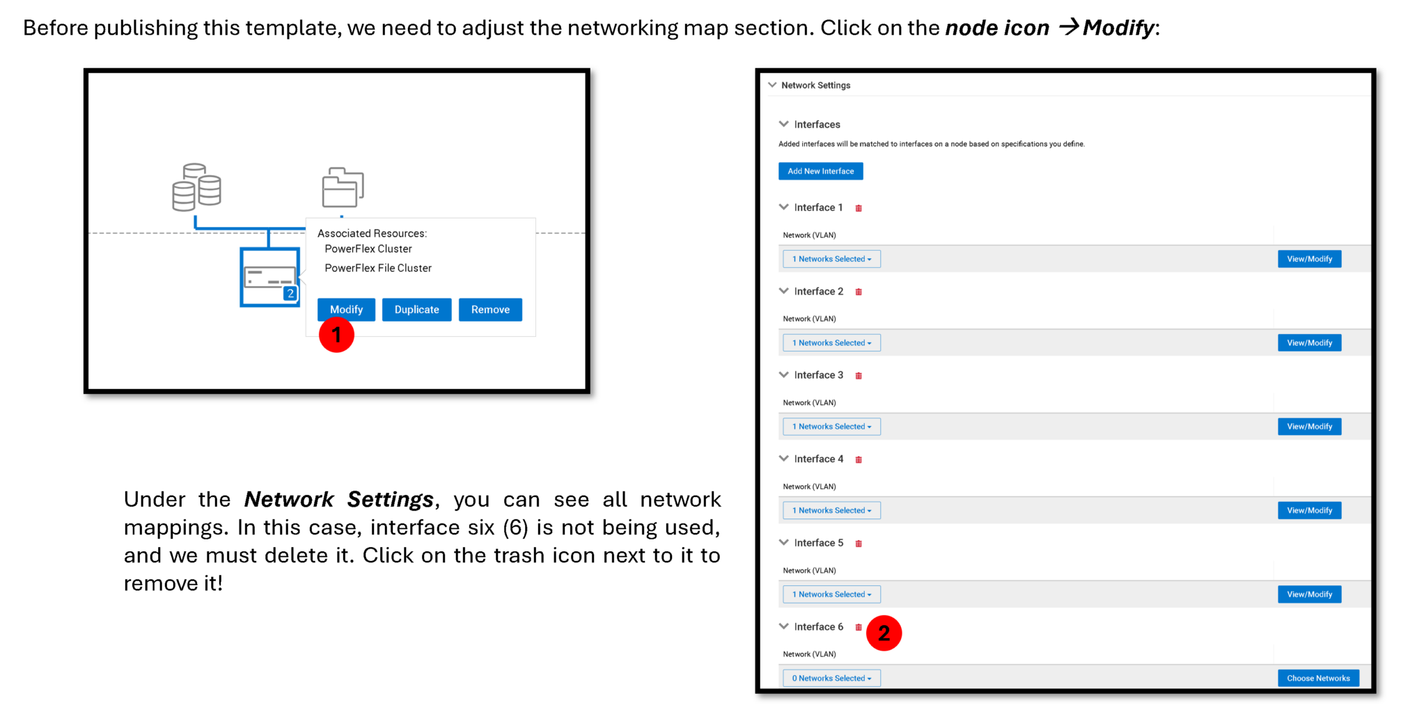
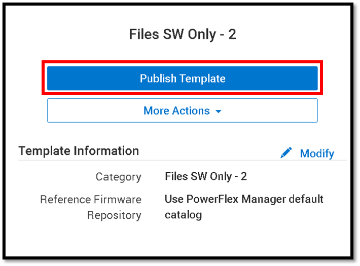
After making all the necessary changes under the new template, click on “Publish Template” to make it usable to deploy new resource groups from this template:
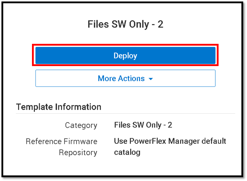
To deploy a new resource group from this template, click on “Deploy”:
Deploy a Resource Group
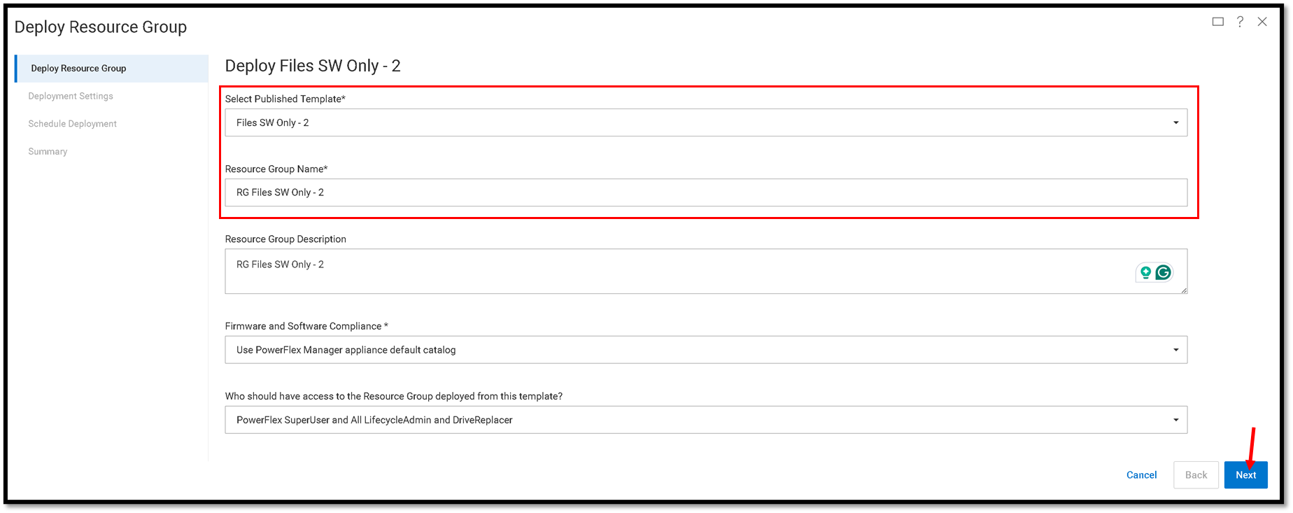
Select the published template under the Deploy Resource Group wizard and type the resource group name. Click on Next to continue:
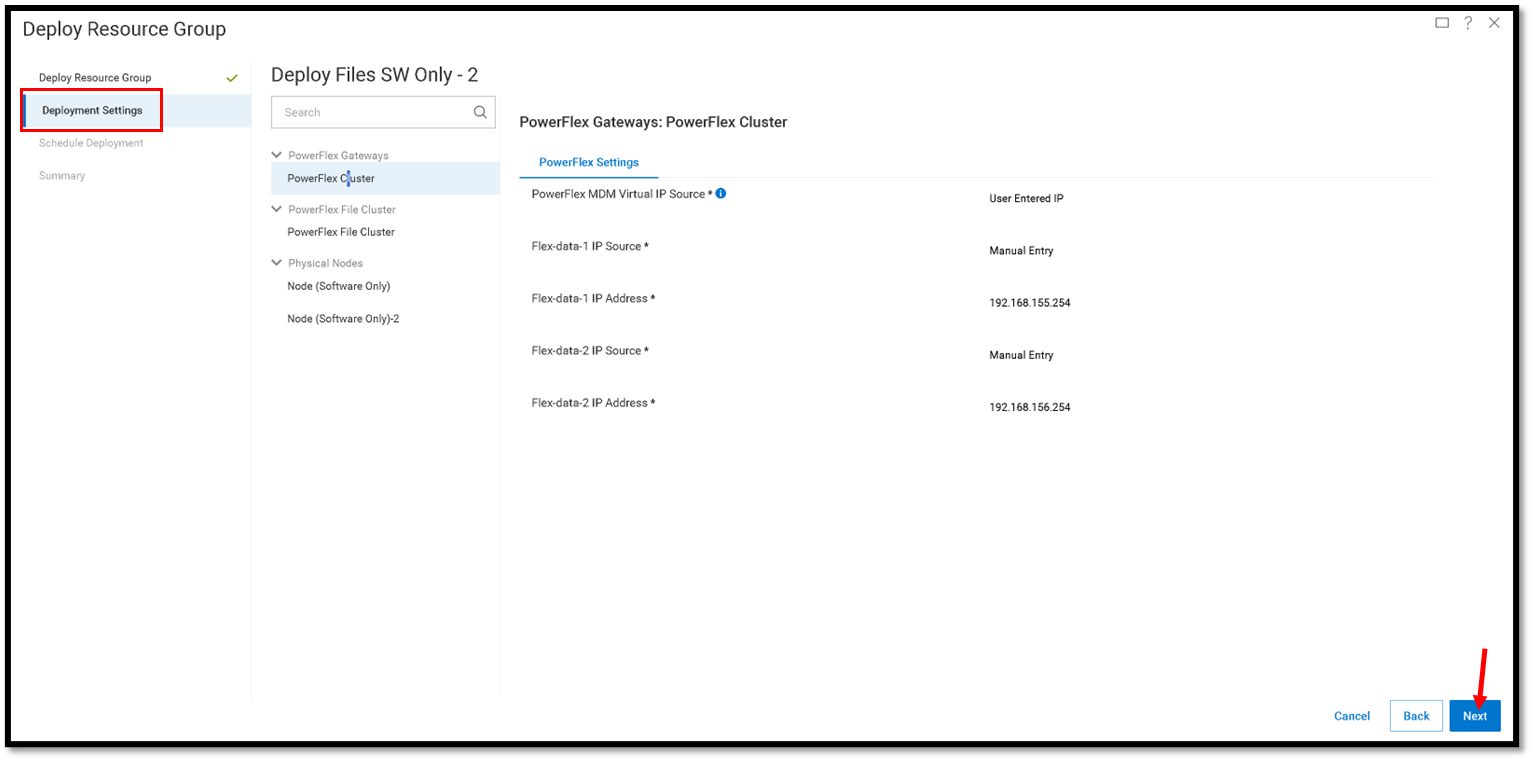
Under the Deployment Settings, keep the default values and click on Next to continue:
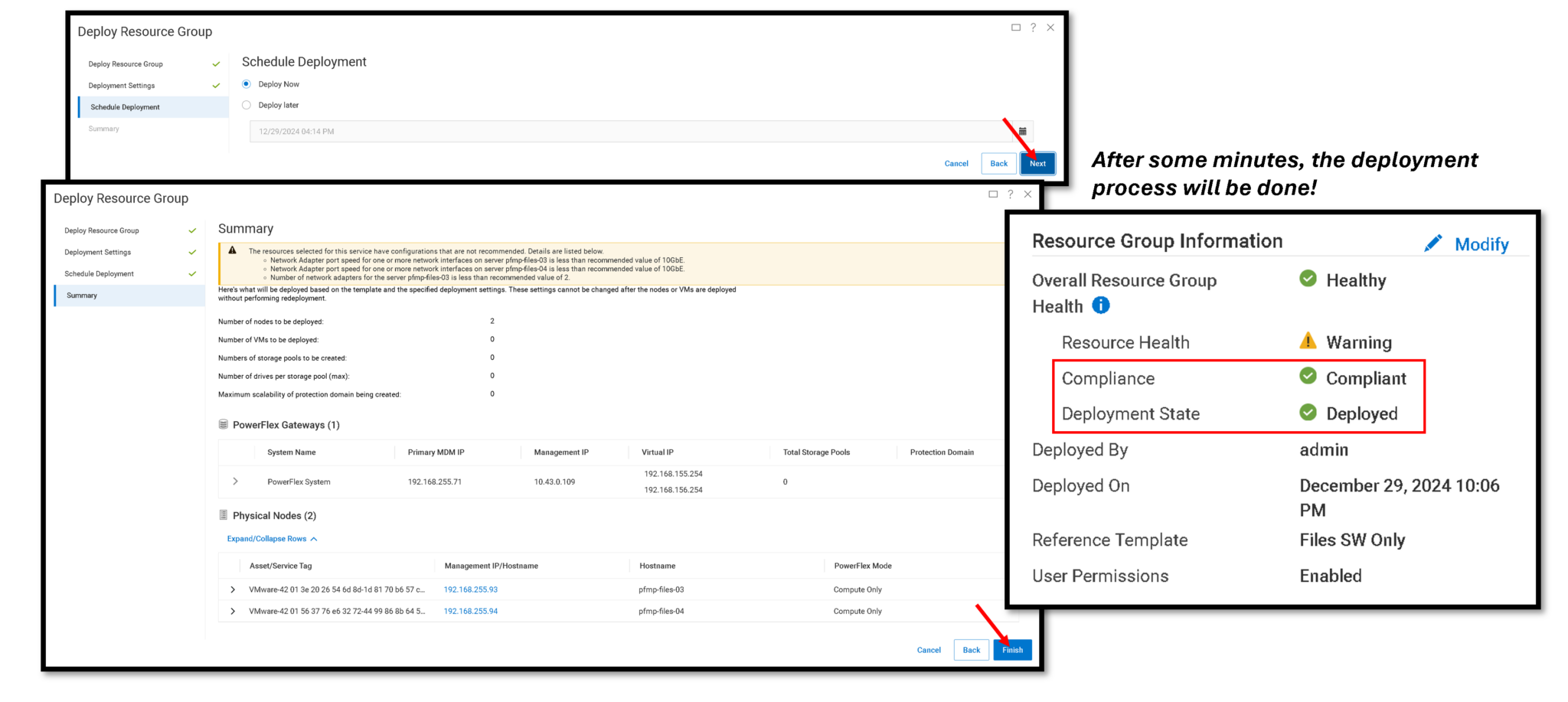
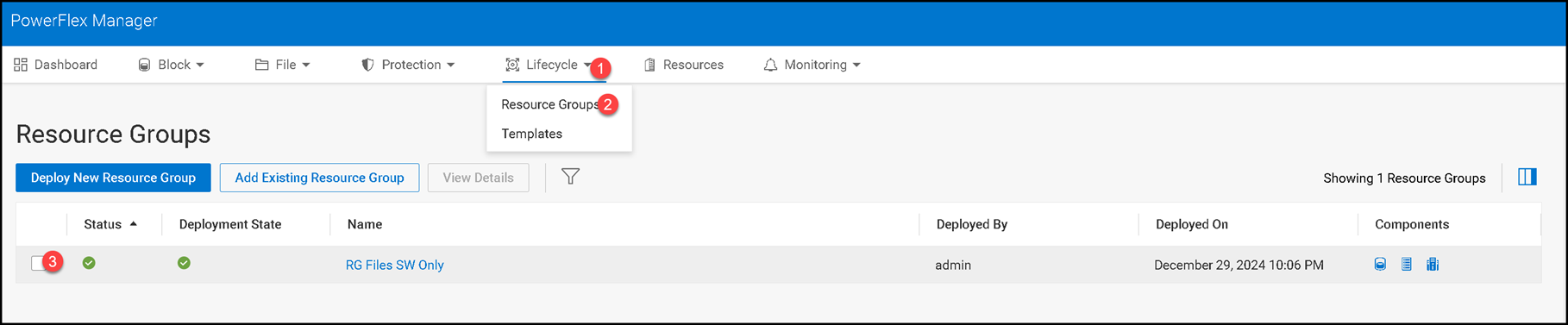
On the Resource Groups page, we can see the deployed Resource Group:
Creating a NAS Server
A NAS Server is a file server that supports the SMB, NFS, FTP, SFTP, or a combination of these protocols to share data with host clients. It also catalogs, organizes, and optimizes read and write operations to the associated file systems.
Access the PowerFlex UI –> File –> NAS Servers –> Create NAS Server:
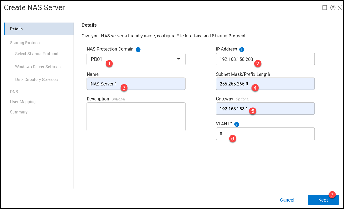
The IP address 192.168.158.200 is from the File Node Management network.
Clients connect to the NAS Server through its production file interface on the NAS File Data network. Keep this client-access address distinct from the PowerFlex Management and NAS File Management networks. Confirm that DNS, routing, VLANs, and client firewall rules allow the intended SMB or NFS traffic to reach the production interface.
Enable the Protocol Type you please and click Next:
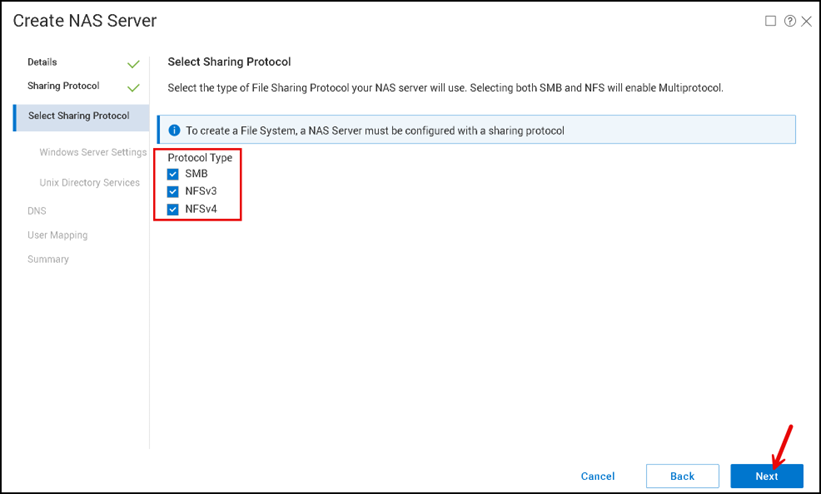
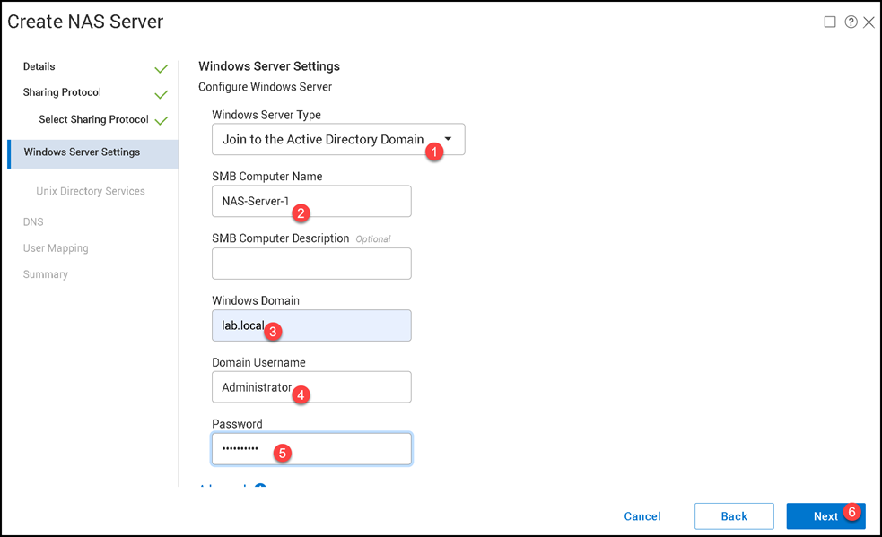
Under the “Windows Server Settings,” we join the NAS Server into our Active Directory Domain. If you don’t have an Active Directory Domain, you can create a standalone domain and follow with the configuration wizard. This step is necessary to enable SMB protocol support:
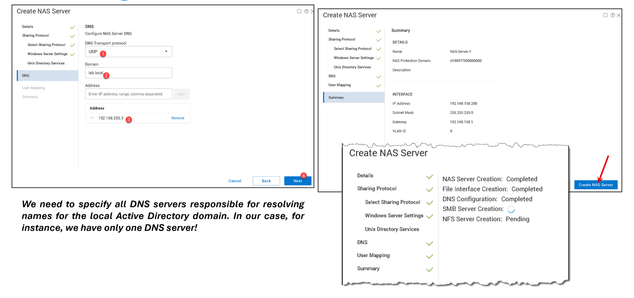
As we can see in the following picture, the NAS Server was created successfully!
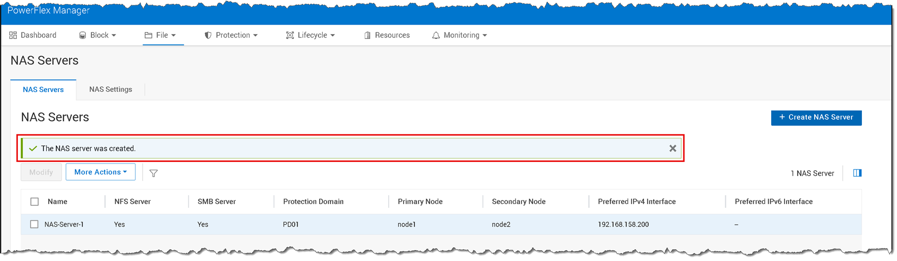
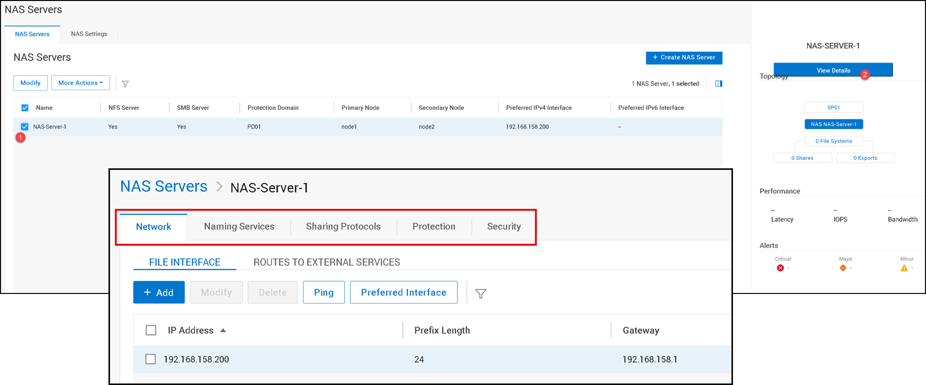
Look at the “Primary Node” and “Secondary Node” details. The created NAS Server runs on both nodes:
— Node 1 is the primary node, and node 2 is the secondary node;
— This means that File Node 1 accepts all clients’ requests, and, in case of failure, File Node 2 will be used for it;
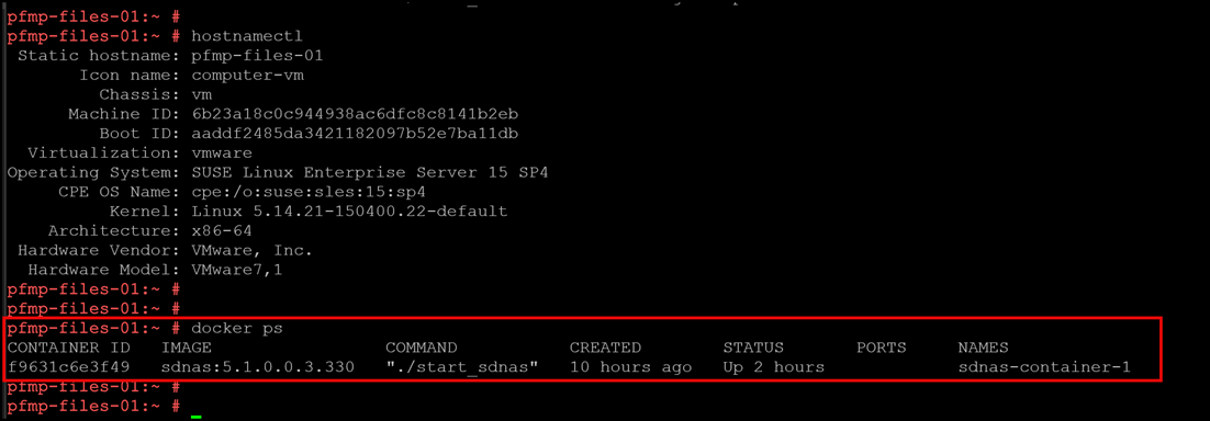
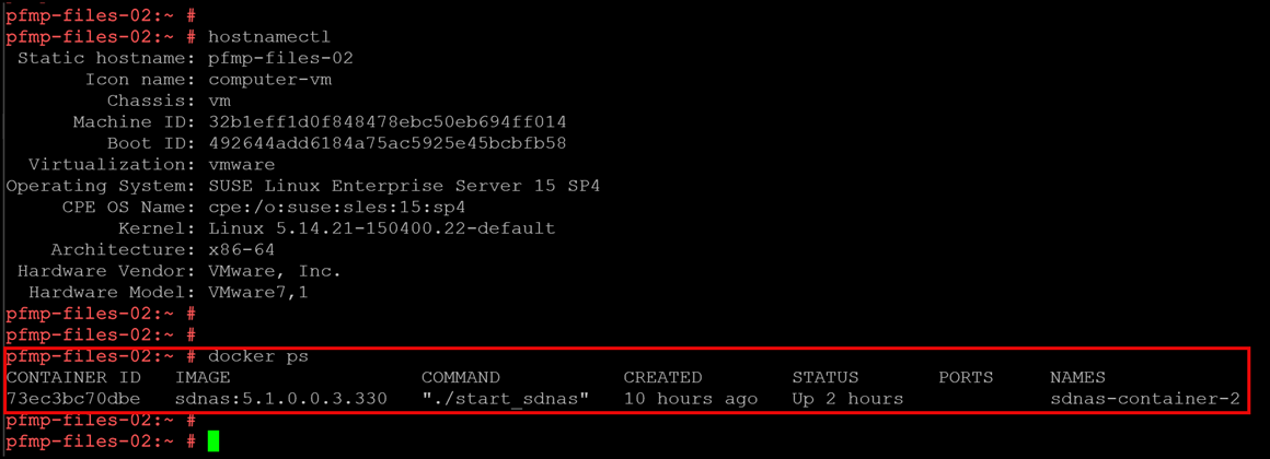
— Inside each File Node, there is a docker container (sdnas containter) responsible for hosting the NAS Server!
SDNAS container on the first File Node:
SDNAS container on the second File Node:
To see all NAS Server’s configurations and details, select the NAS Server and click on “View Details”:
Creating a File System
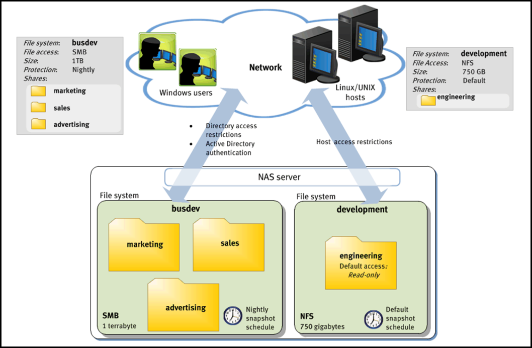
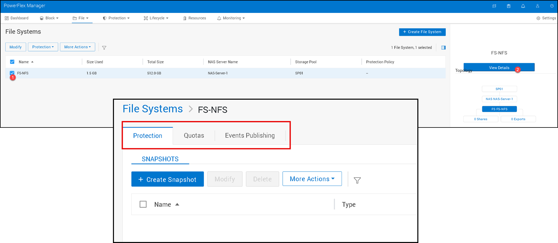
A File System represents a set of storage resources that provide network file storage. The storage system establishes a file system that Windows users or Linux/UNIX hosts can connect to and use for file-based storage. Users access a file system through its shares, drawing from the total storage allocated to the file system:
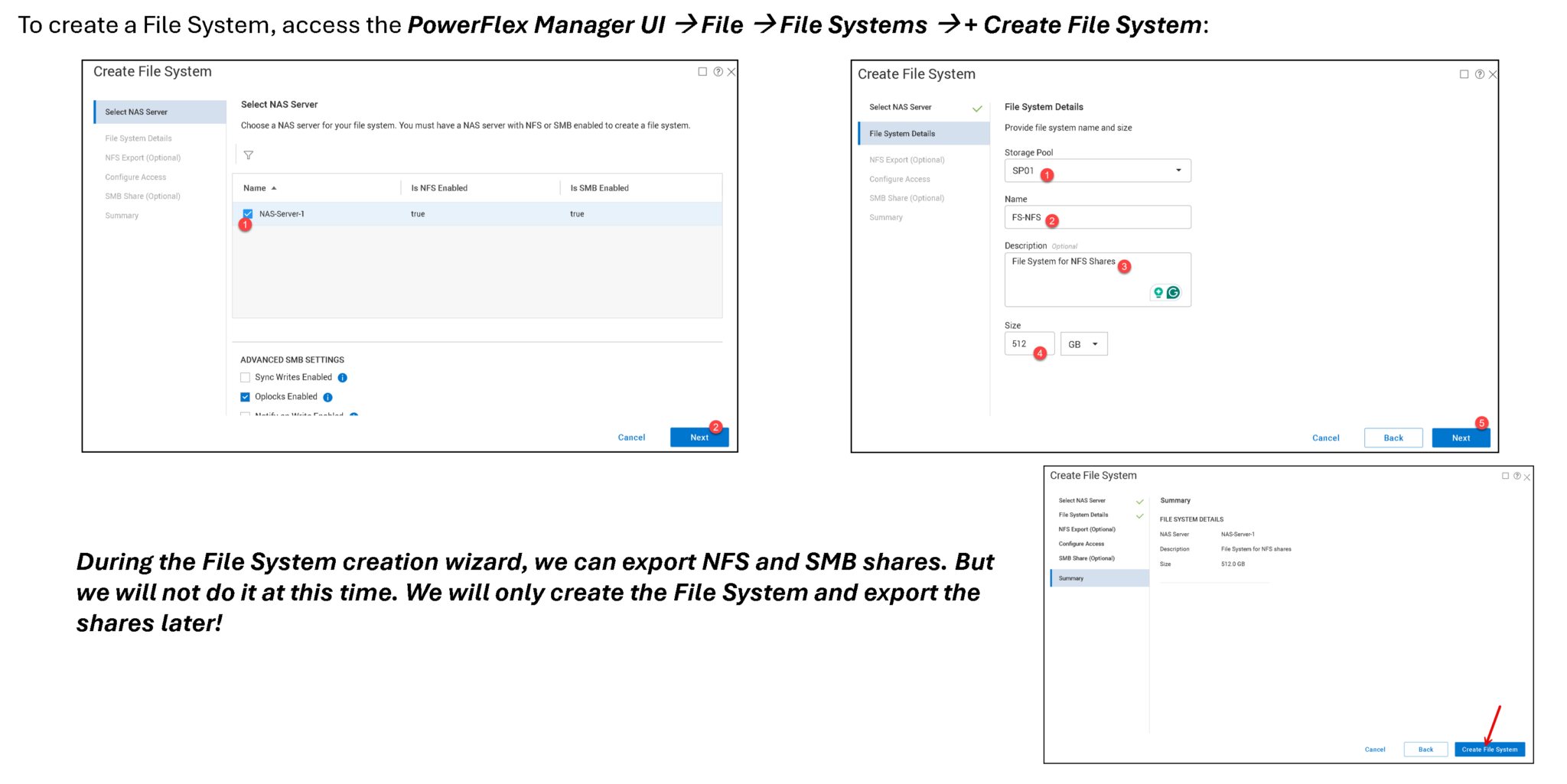
To check File Systems’ details and configurations, select the File System and click “View Details”:
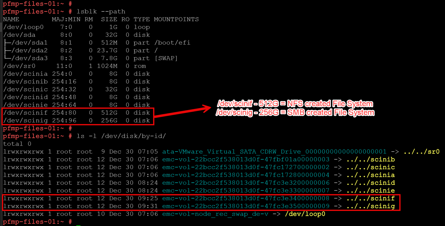
On both File Nodes (node1 and node2), we can identify both volumes used by creating the File Systems:
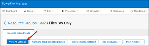
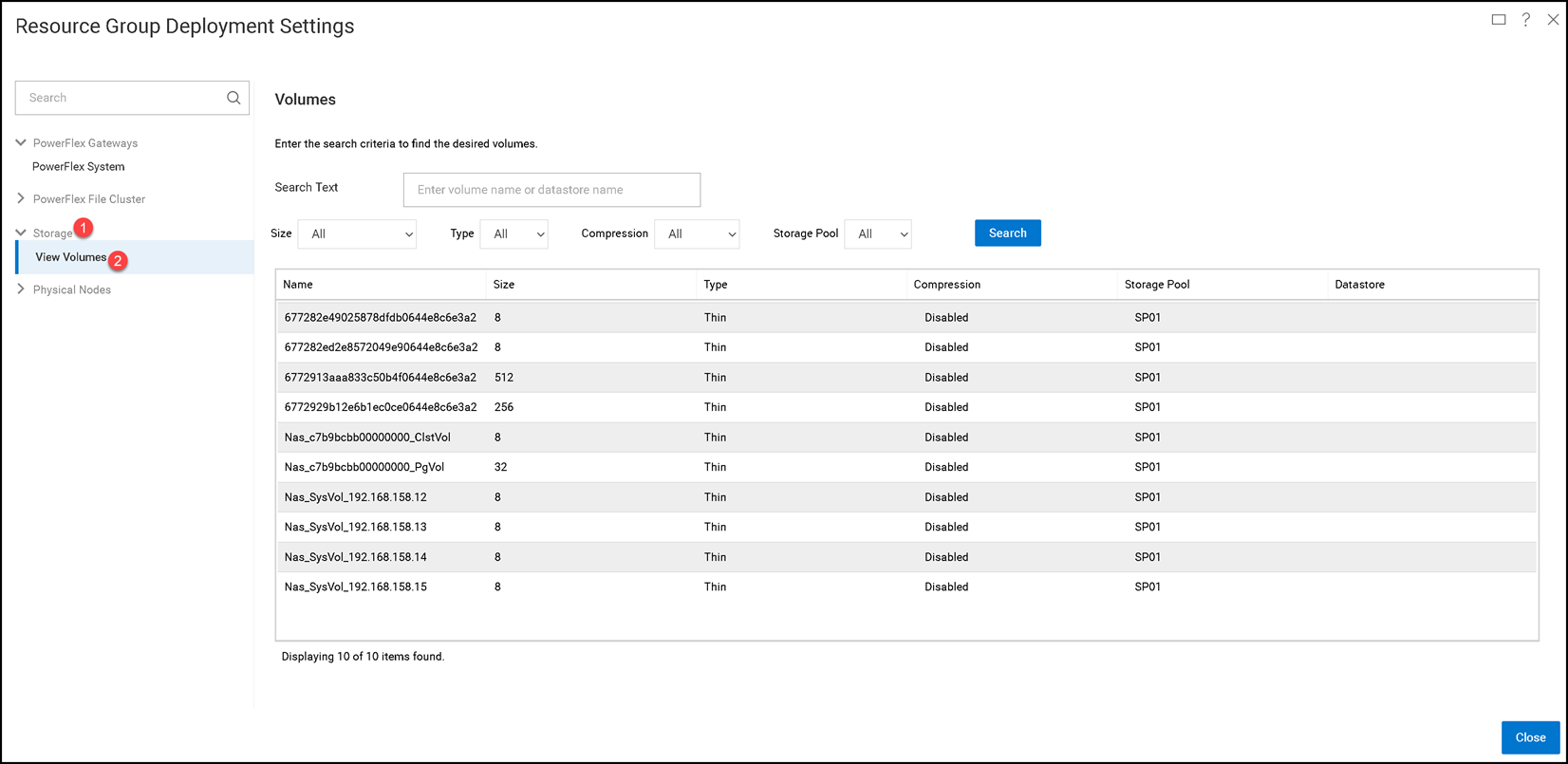
To see all Volumes used by the File Services, go to the created Resource Group and click on “View All Settings”:
Creating an SMB Share
To create a SMB share, access the PowerFlex Manager UI –> Files –> SMB Shares –> + Create SMB Share:
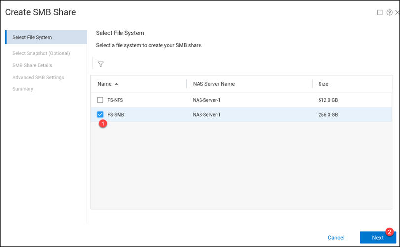
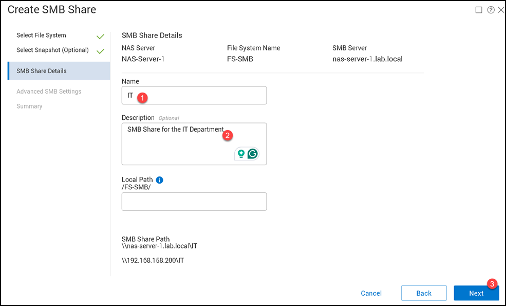
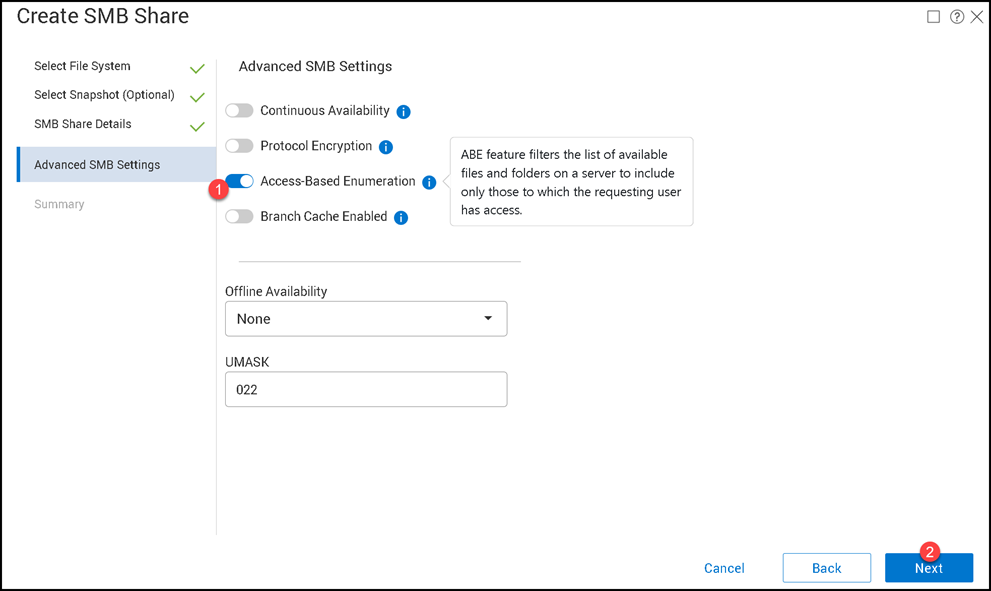
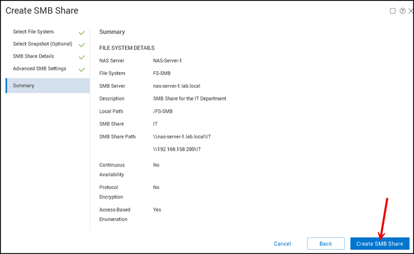
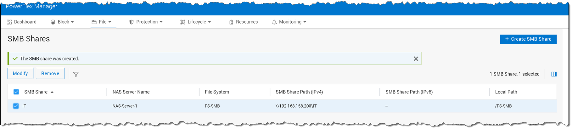
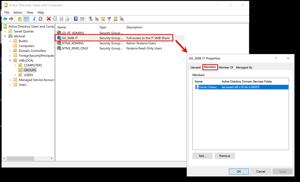
Since our NAS Server is joined into the Active Directory, we will control the share access through Users and Groups of the Active Directory:
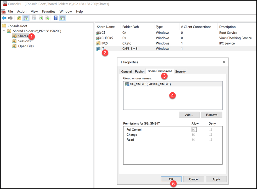
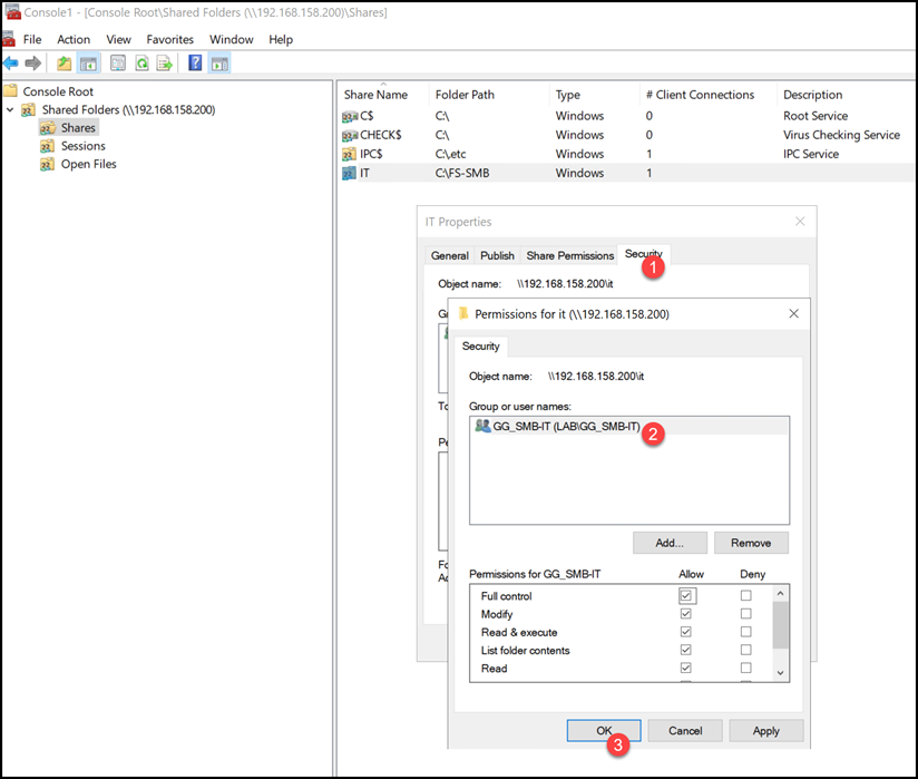
To adjust the SMB share permission, go to a Windows machine (joined at the AD domain), open the “mmc” and add the Shared Folders utility, pointing to the NAS Server, as we can see in the following pictures:
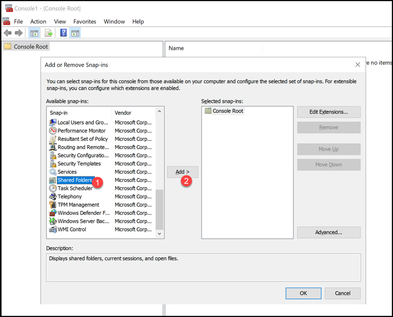
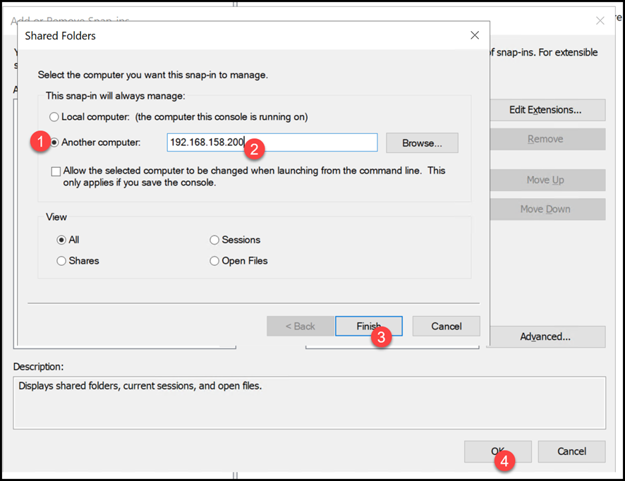
Adjust the share and file system (NTFS) permission as necessary. In this example, only all users from the Group “GG_SMB-IT” have full access to the “IT” SMB share:
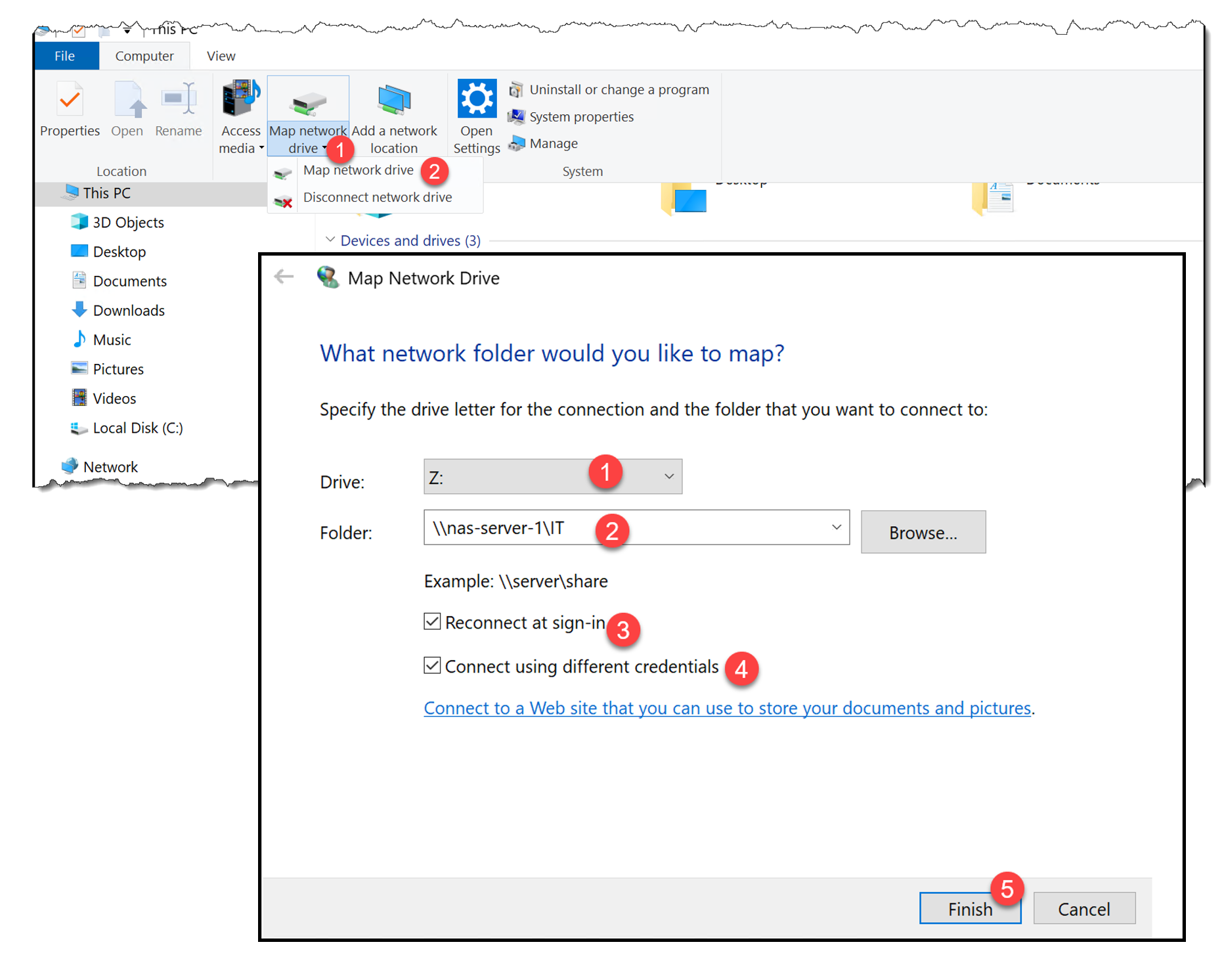
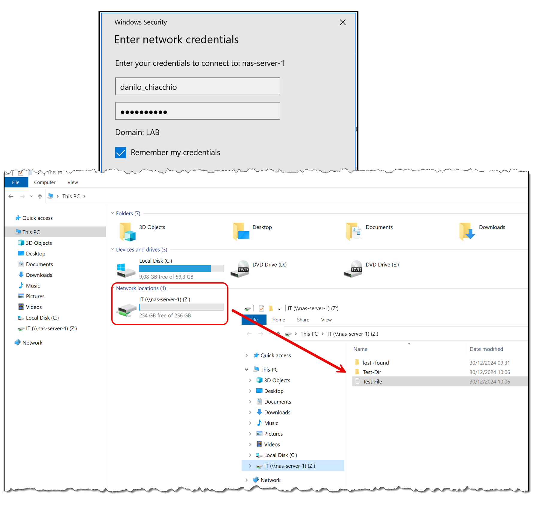
Mounting the “IT” SMB share on a Windows machine:
Creating an NFS Share
To create a NFS share, access the PowerFlex Manager UI –> Files à NFS Exports –> + Create NFS Export:
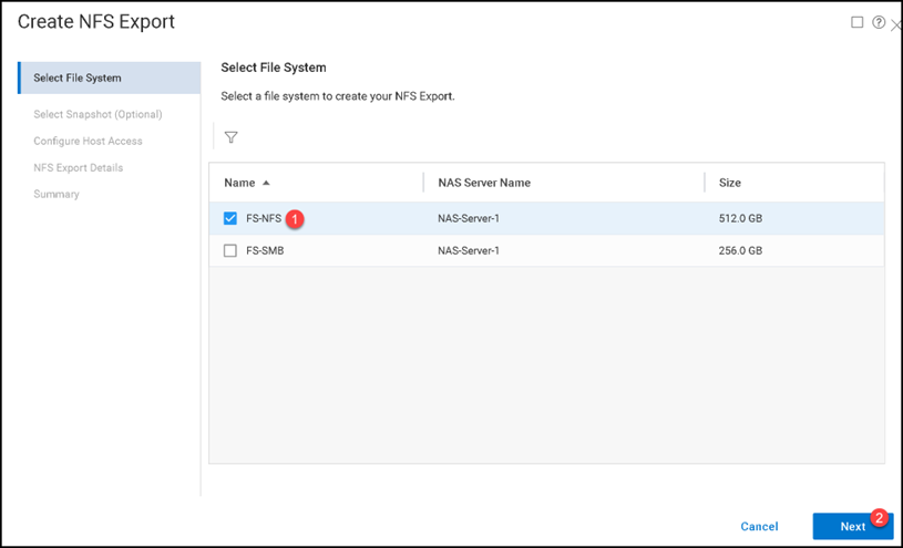
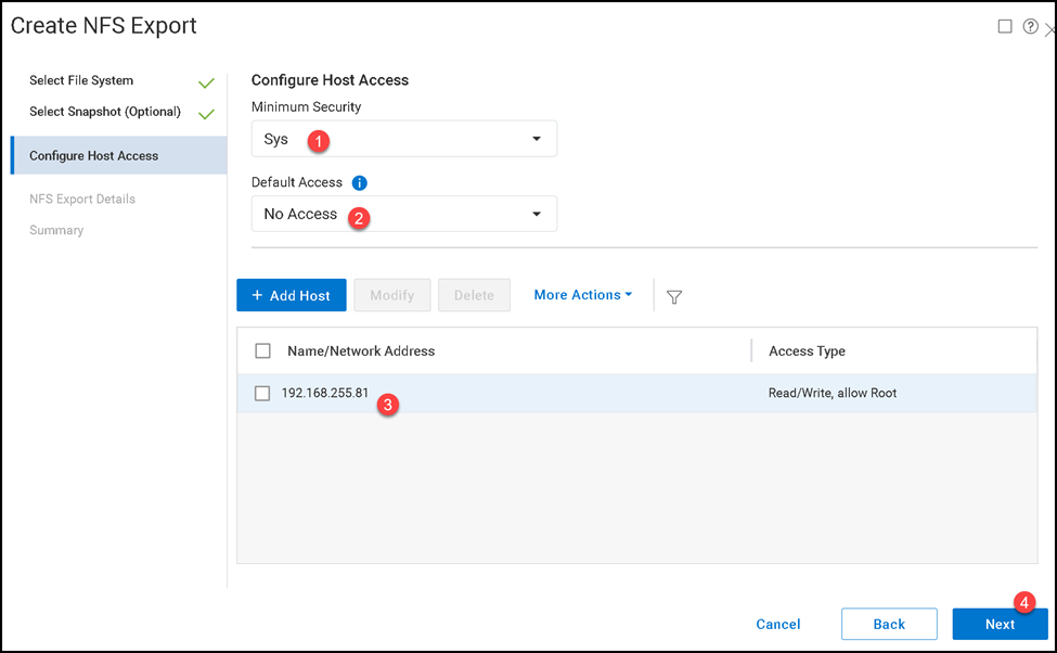
Type the NFS Export name and description and click on “Create NFS Export”:
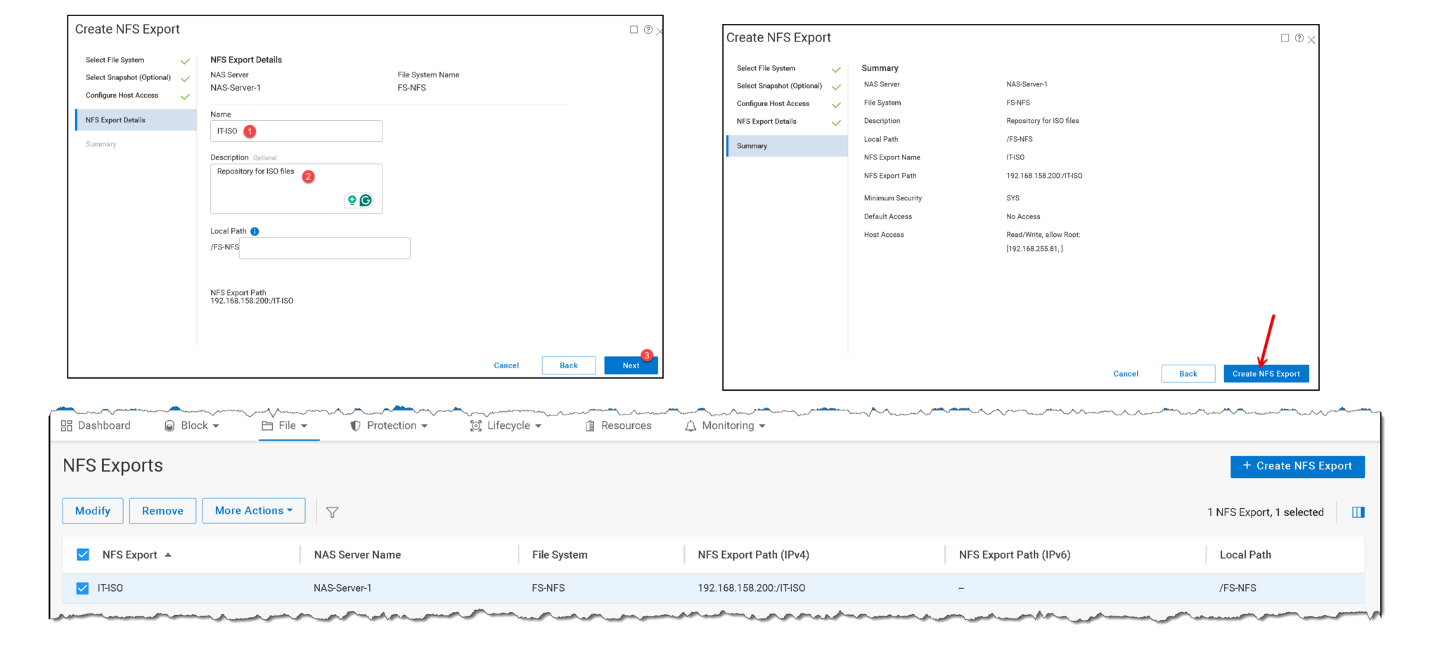
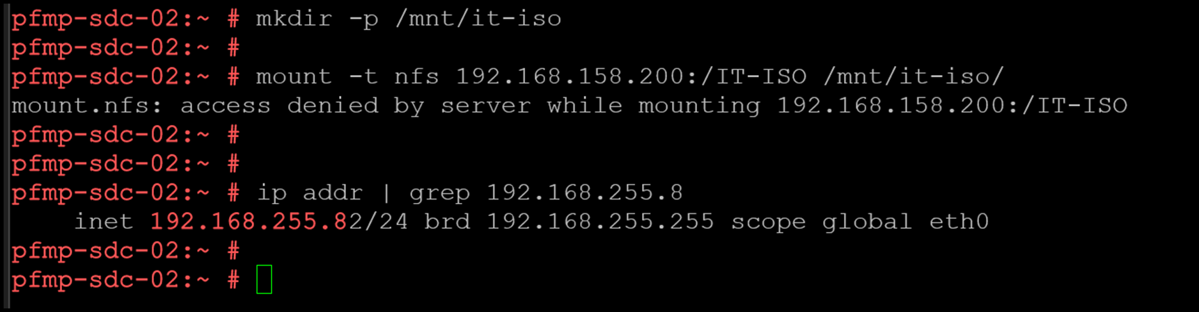
To mount the NFS share, access the client computer and mount it using the following command:
mount -t nfs 192.168.158.200:/IT-ISO /mnt/it-iso/

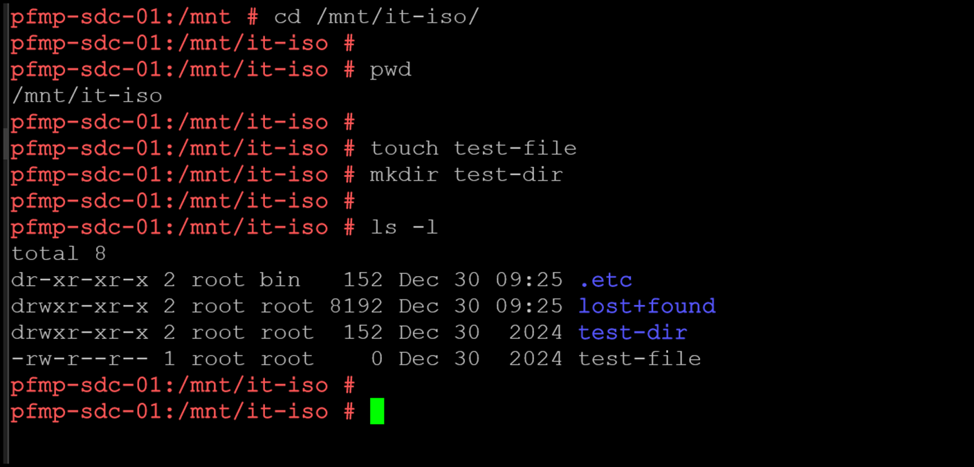
During the NFS Export creation, we defined only the host with IP address 192.168.255.81 with permission to mount the directory. If we try to mount from another host, we will have an error, as we can see in the following picture:
What This Lab Demonstrates
This walkthrough shows the end-to-end PowerFlex File Services workflow: prepare and deploy File Nodes, create a NAS Server and file system, and expose data through SMB shares or NFS exports. The client-facing address must belong to a production file interface on the NAS File Data network, while management networks remain separate.
Before adapting the workflow to another environment, verify the supported File Node platform, network roles, NAS Server protocols, and client permissions for the exact PowerFlex release. Treat the nested setup as a lab demonstration, and use Dell’s release-specific documentation for any production deployment.
External References
- Dell — Deploying PowerFlex File Nodes PowerFlex 4.5.x deployment guide covering File Services terminology, File Nodes, NAS Servers, SMB/NFS file access, and the documented File Node platform requirements.
- Dell — Define Networks for PowerFlex Manager Explains the PowerFlex Management, NAS File Management, and NAS File Data network types, including their separate roles in deployment and client file access.
- Dell — Overview of Configuring NAS Servers Describes the NAS Server role and its use for file sharing with clients in PowerFlex 4.5.x.
- Dell — NAS Servers Documents NAS Server creation, SMB and NFS protocol choices, primary/secondary node assignment, and configuration management in the PowerFlex UI.
- Dell — Create an SMB Share Official PowerFlex 4.5.x steps for creating an SMB share on a file system associated with an SMB-enabled NAS Server.
- Dell — Create an NFS Export Official PowerFlex 4.5.x steps for creating an NFS export on an NFS-enabled file system and defining its client access.
- Dell — About File Systems Explains how SMB/NFS protocol support on a NAS Server determines the file systems, SMB shares, and NFS exports that can be provisioned.
