
Replacing a failed disk in a PowerFlex Storage Data Server (SDS) involves more than swapping the hardware. First identify the affected device and its Storage Pool, then remove it through the supported PowerFlex workflow and wait for the data-protection and removal tasks to complete. Only then replace the physical drive, identify the new device by its hardware details, and add it back to the correct SDS and Storage Pool.
This walkthrough uses a PowerFlex Software-Only lab with Linux SDS nodes running SUSE Linux Enterprise Server (SLES) 15 SP4. It demonstrates how a disk error is detected, how the failed device is removed, and how a replacement device is added and verified. The process can trigger data movement, rebuild, or rebalance activity and may take time. The exact procedure depends on the PowerFlex release, node type, disk controller, and server hardware, so verify the applicable Dell support matrix and service instructions before using it in production.
Important: This is a lab walkthrough, not a substitute for the Dell procedure that applies to your PowerFlex release and hardware. Before removing a device, confirm that the cluster and remaining SDSs are healthy, that the affected device is correctly identified, and that the Storage Pool has sufficient protection and capacity for the required data movement. Do not remove or pull a drive until the PowerFlex removal task has completed successfully. Never run the failure-simulation command shown below on a production system.
Check the cluster and identify the affected SDS device
1- Connect to the management system and authenticate to SCLI. Check the SDS status before starting. The example below uses the lab hostname; replace it with the management-system address for your environment:
scli –login –management_system_ip pfmp.lab.local –username admin
scli –query_all_sds
Confirm that the SDS nodes are connected and that the cluster is in an acceptable state. Do not proceed if there are unresolved cluster issues or other storage-maintenance tasks in progress:

Record the device ID, path, and Storage Pool
2- The next recommended step is to check the disk status of each SDS node. We can do it by executing the following command:
scli --query_sds --sds_name SDS01 | egrep -i "Path:|State:"In this example, the SDS named “SDS01” has three disk devices, and their status is “Normal” (it means each device is working fine):

Note: We can repeat the same command by replacing the SDS node name to check the disk status for the other SDSs:
scli --query_sds --sds_name SDS02 | egrep -i "Path:|State:“
scli --query_sds --sds_name SDS03 | egrep -i "Path:|State:“
scli --query_sds --sds_name SDS04 | egrep -i "Path:|State:“
scli --query_sds --sds_name SDS05 | egrep -i "Path:|State:“
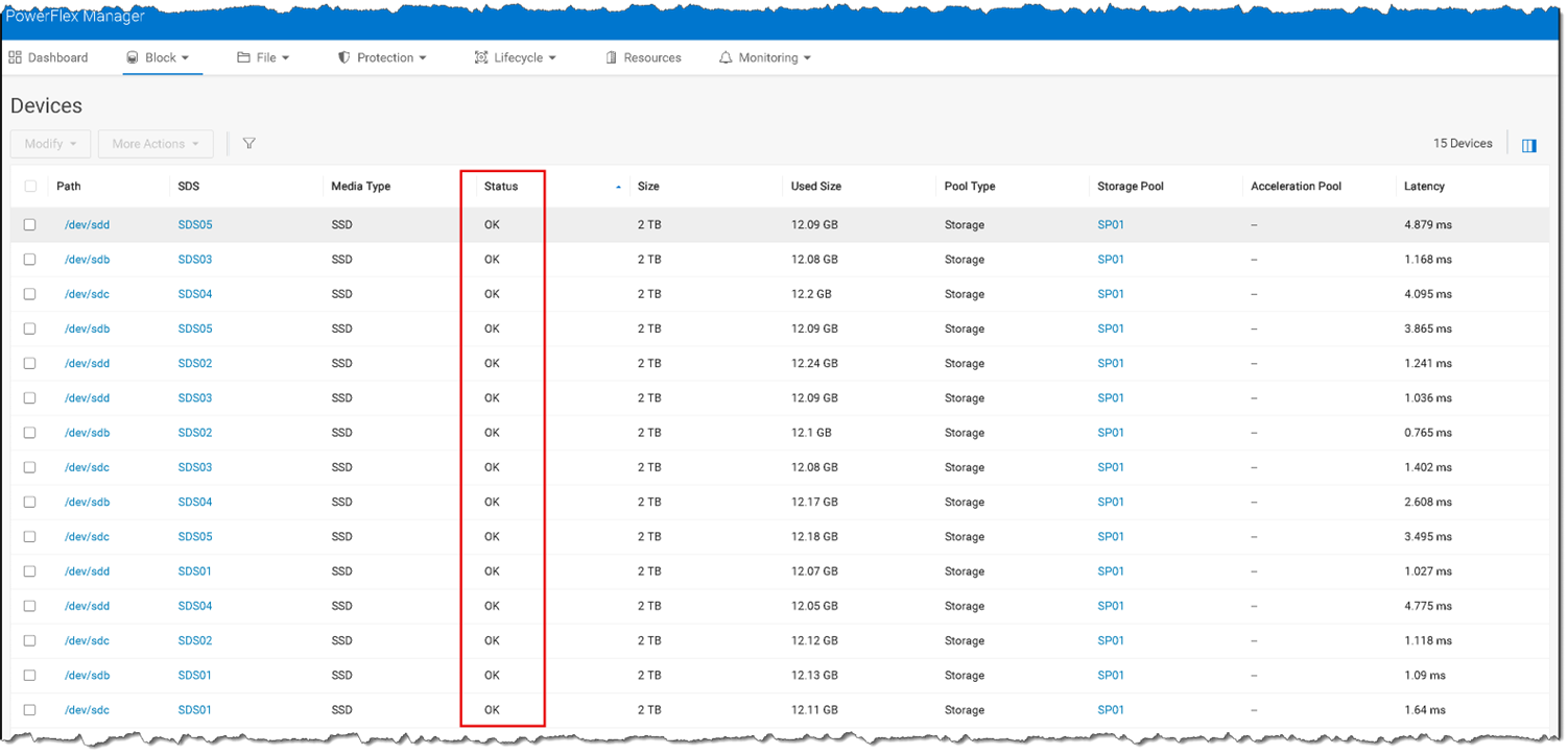
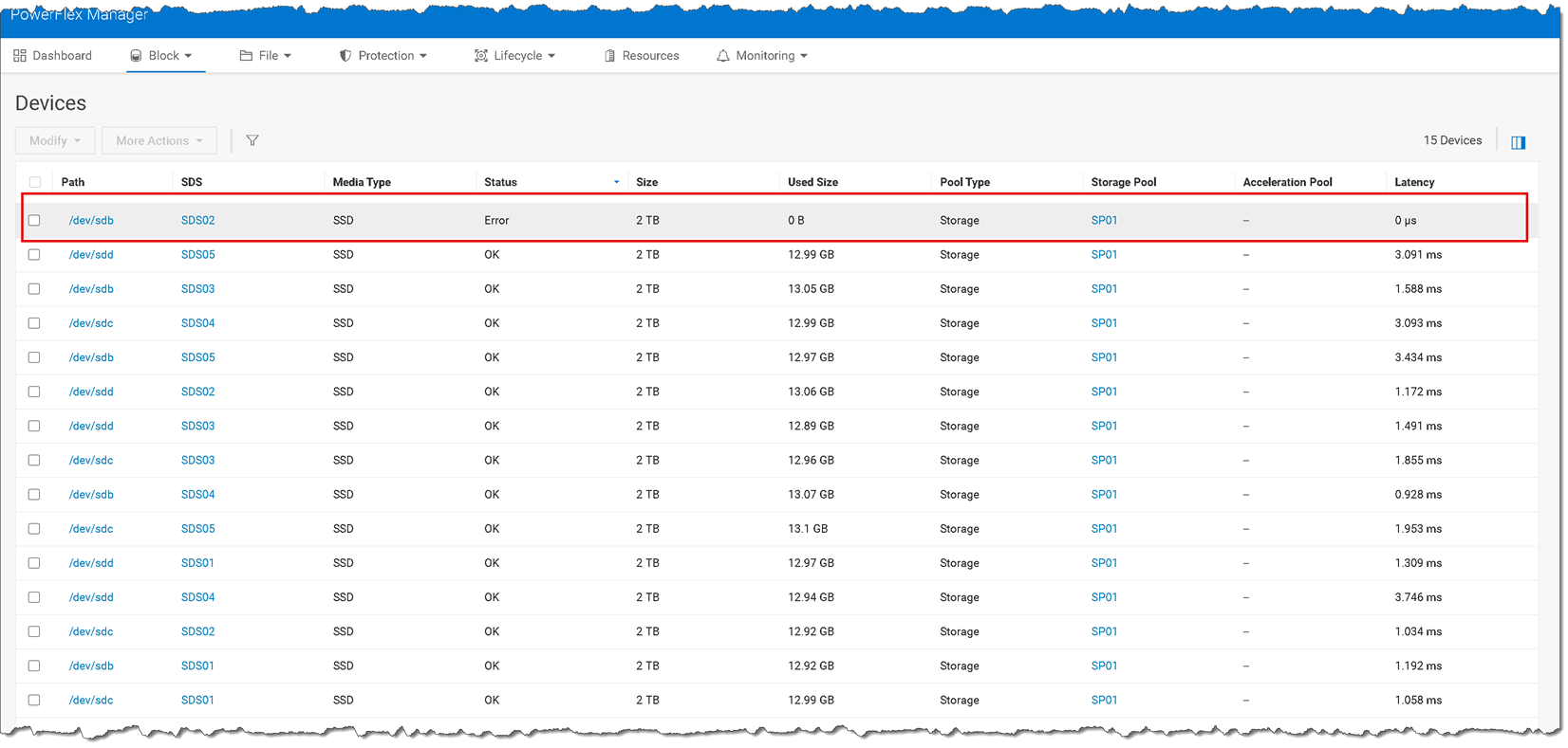
3- Another way to check the status of the disks is through the PowerFlex Manager UI. Access the PowerFlex Manager UI à Block à Devices à Look at the “Status” column:
Lab-only failure simulation — keep the restriction next to the command
4- The original command writes to the Linux SCSI device’s state attribute. It takes that device offline at the operating-system layer; it is not a production disk-replacement procedure and can immediately interrupt access to the device. Keep this step only if the article is explicitly demonstrating an isolated lab simulation.
**Lab only:** Run this only against a disposable virtual disk assigned to the test SDS. Verify the disk path and hardware identity first. This command takes the Linux SCSI device offline and can cause I/O errors and a PowerFlex device alert.
Do not run it on a production host or on any disk whose identity is uncertain.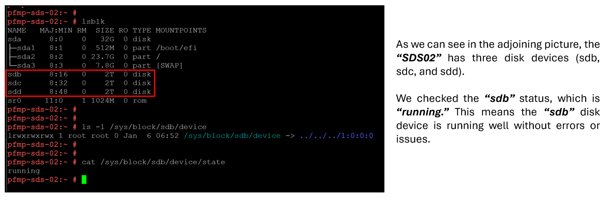
5- Simulate a disk failure on the “sdb” disk device:
# Lab-only simulation on the disposable test device /dev/sdb
sh -c 'printf "%s\n" offline > /sys/block/sdb/device/state'

or

echo "offline" > /sys/block/sdb/device/state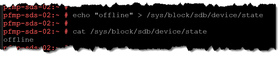
After the simulation, query the SDS devices again and confirm that the intended disk is the one reporting an error:
scli --login --management_system_ip pfmp.lab.local --username admin
scli --query_sds --sds_name SDS02 | egrep -i "Path:|State:"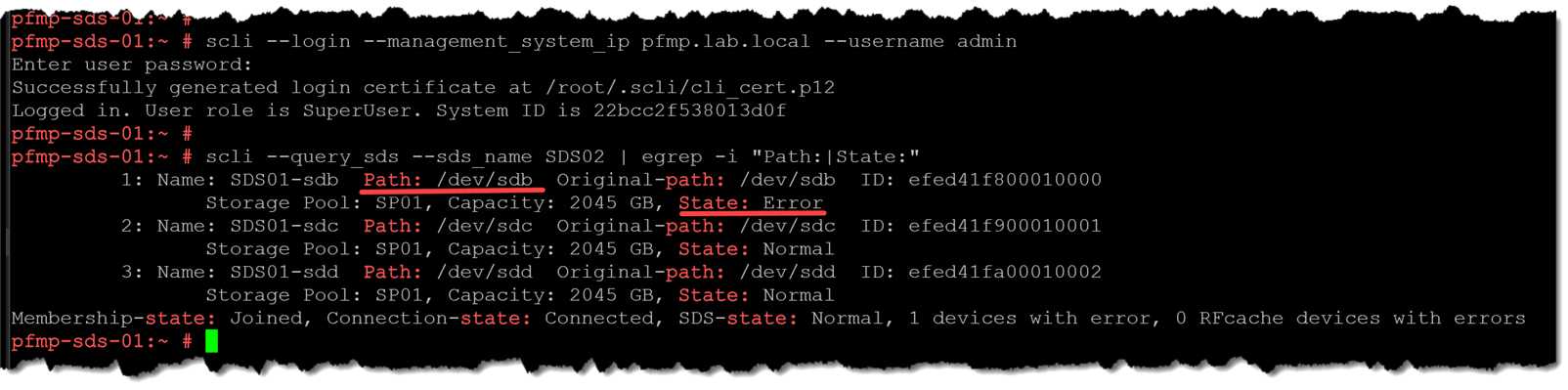
6- We can also confirm through the PowerFlex Manager UI that the disk “sdb” has an “error” status:
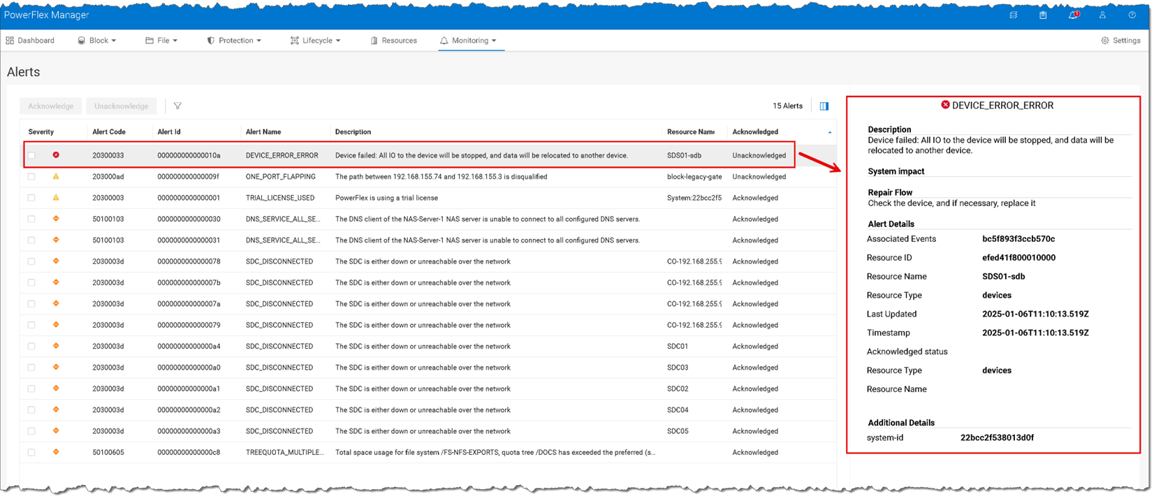
7- Under the Monitoring –> Alerts menu, we can see the disk failure alert as well:
Remove the failed device from PowerFlex
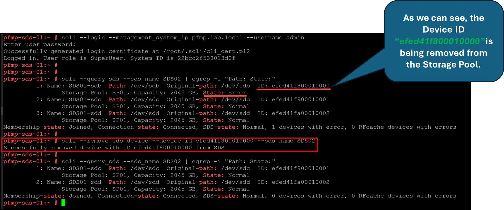
8- Remove the faulty device from the Storage Pool:
scli --login --management_system_ip pfmp.lab.local --username admin
scli --query_sds --sds_name SDS02 | egrep -i "Path:|State:“
scli --remove_sds_device --device_id efed41f800010000 --sds_name SDS02Note: The removal is asynchronous. PowerFlex may need to replicate the data associated with the device to other nodes, so the task can take a long time. Monitor its progress in PowerFlex Manager or with the documented SCLI queries. Wait until the removal has completed successfully before physically removing the drive. If removal fails because the pool cannot evacuate the device’s used capacity, stop and investigate; do not force the operation or pull the disk as a workaround.
For an SDS-device replacement, use the applicable software-only device-removal workflow. Do not put the SDS into Protected Maintenance Mode before removing the device: Dell’s manual-replacement instructions note that the device cannot be removed while the node is in that mode:
Replace the physical drive
9- After PowerFlex has completed the device-removal task, replace the physical drive according to the server manufacturer’s service manual. Hot-swap is appropriate only when the server, drive bay, controller, and current operating conditions support it.
If the server must be shut down for the hardware work, review Safely Reboot a PowerFlex Node: MDM and SDS Maintenance Steps for the planned single-node maintenance workflow. Follow the Dell procedure for your specific hardware and PowerFlex release when replacing the physical drive.
If the hardware procedure requires powering off the host, plan that separately and follow the node-maintenance procedure for the applicable PowerFlex release. Do not assume that every SDS drive can be replaced while the server is running:
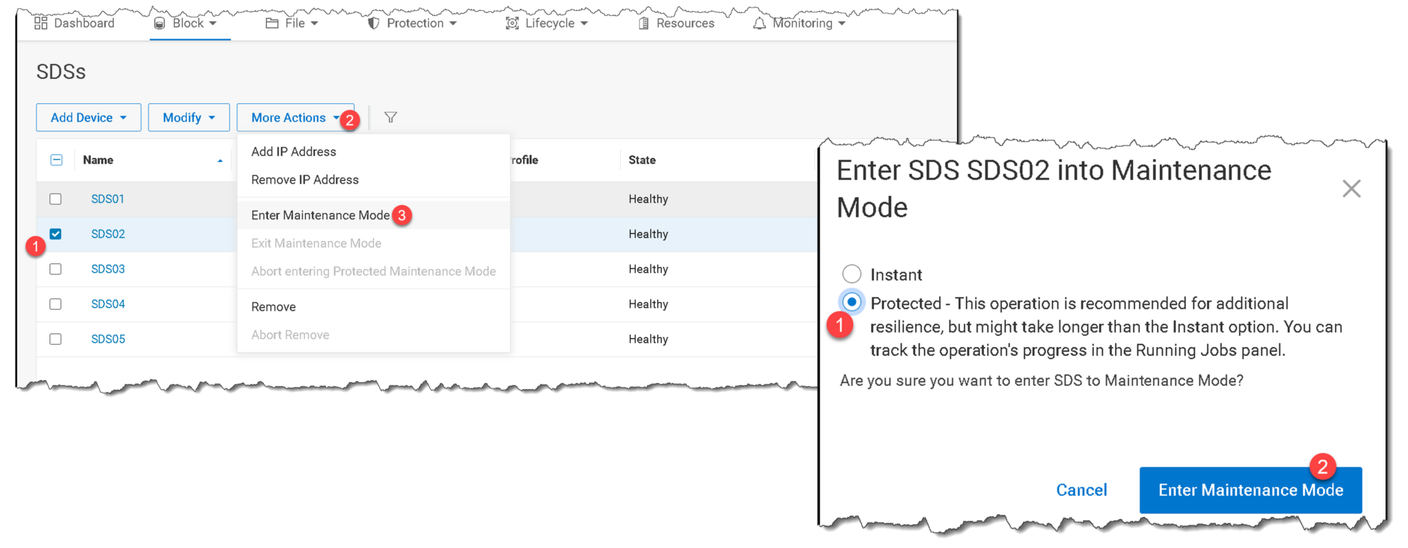
10- Do not assume the replacement will receive the same /dev/sdX name. Check its size, model, serial number, and persistent identifier, then match those values to the physical drive you installed:
lsblk --output NAME,SIZE,MODEL,SERIAL,WWN
ls -l /dev/disk/by-id/
In this lab, the replacement was detected as /dev/sdd. Use the actual path observed on your SDS. Confirm that the device is the intended replacement and is clear for PowerFlex use. Do not add a disk that contains a filesystem, partitions, LVM membership, or data that must be retained.
Add the replacement disk to the original SDS and Storage Pool
Replace the sample path, SDS name, device name, and Storage Pool with the values recorded for your environment. The device name is a label for identification; keep it unique and descriptive:
scli --add_sds_device --sds_name SDS02 --device_path /dev/sdd --device_name SDS02-sdd --storage_pool_name SP01PowerFlex tests the new device by default before its capacity is made available. Allow the task and any resulting data movement to finish. Do not add --force_device_takeover unless you intentionally want to destroy existing data on the selected device and have verified that this is the correct action.
As we can see in the following picture, the new disk has been added successfully:

All disks for this SDS node are “Normal” (running fine):

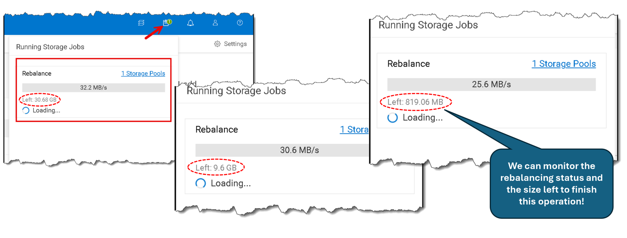
Confirm that the replacement appears under the expected SDS and Storage Pool and that its device state is Normal. Check PowerFlex Manager for running storage jobs and alerts. A rebuild or rebalance may take time; wait for the jobs to finish and verify the system is healthy before closing the maintenance activity.
If the node was placed in a maintenance or service mode as part of the hardware procedure, exit that mode only after the replacement disk is recognized and the node is ready. Follow the release-specific Dell workflow and verify the SDS returns to a healthy state:
Note: If your goal is to increase Storage Pool capacity rather than replace a failed drive, see Scale Out PowerFlex Storage: Adding Disks to Existing SDS Nodes. That walkthrough covers adding available disks to existing SDS nodes; it is a different operation from removing and replacing a failed device.
To Wrap this Up
A failed SDS disk is replaced only after the old device has been removed through PowerFlex and the replacement has been added to the correct SDS and Storage Pool. Before returning the system to normal operations, confirm that the new device is healthy, any rebuild or rebalance activity has completed, and the cluster reports no unresolved alerts.
These checks help distinguish a completed hardware swap from a completed storage recovery. For production systems, use the Dell instructions for the exact deployment and hardware model, and do not proceed when the cluster’s health or remaining capacity is uncertain.
External References
- Dell — PowerFlex: Steps to Manually Replace a Hard Drive Current Dell guidance for removing a failed storage device through PowerFlex Manager before physical replacement, identifying the replacement path, and adding the new drive back to the SDS.
- Dell — remove_sds_device Command PowerFlex 4.5.x CLI reference for removing an SDS device, including its asynchronous behavior, data replication during removal, and progress queries.
- Dell — query_sds_device_info Command Documents how to retrieve device IDs, paths, Storage Pool assignments, capacity, and state for all devices in a specified SDS.
- Dell — add_sds_device Command PowerFlex 4.5.x command syntax for adding a storage device to an SDS and Storage Pool, including device-clear checks, default testing, and the data-destruction warning for force takeover.
- Dell — Add Storage Devices PowerFlex 4.5.x installation and upgrade guide describing the SCLI workflow for adding storage devices to SDS nodes.
- Dell — PowerFlex Operating-System Support Matrix Lists supported PowerFlex, operating-system, and component combinations. Check the exact release and SDS component before using SLES 15 SP4 in a production deployment.
- Linux Kernel — SCSI Interfaces Guide Kernel documentation describing SCSI device state transitions, relevant to the lab-only failure simulation that takes a SCSI device offline.
