
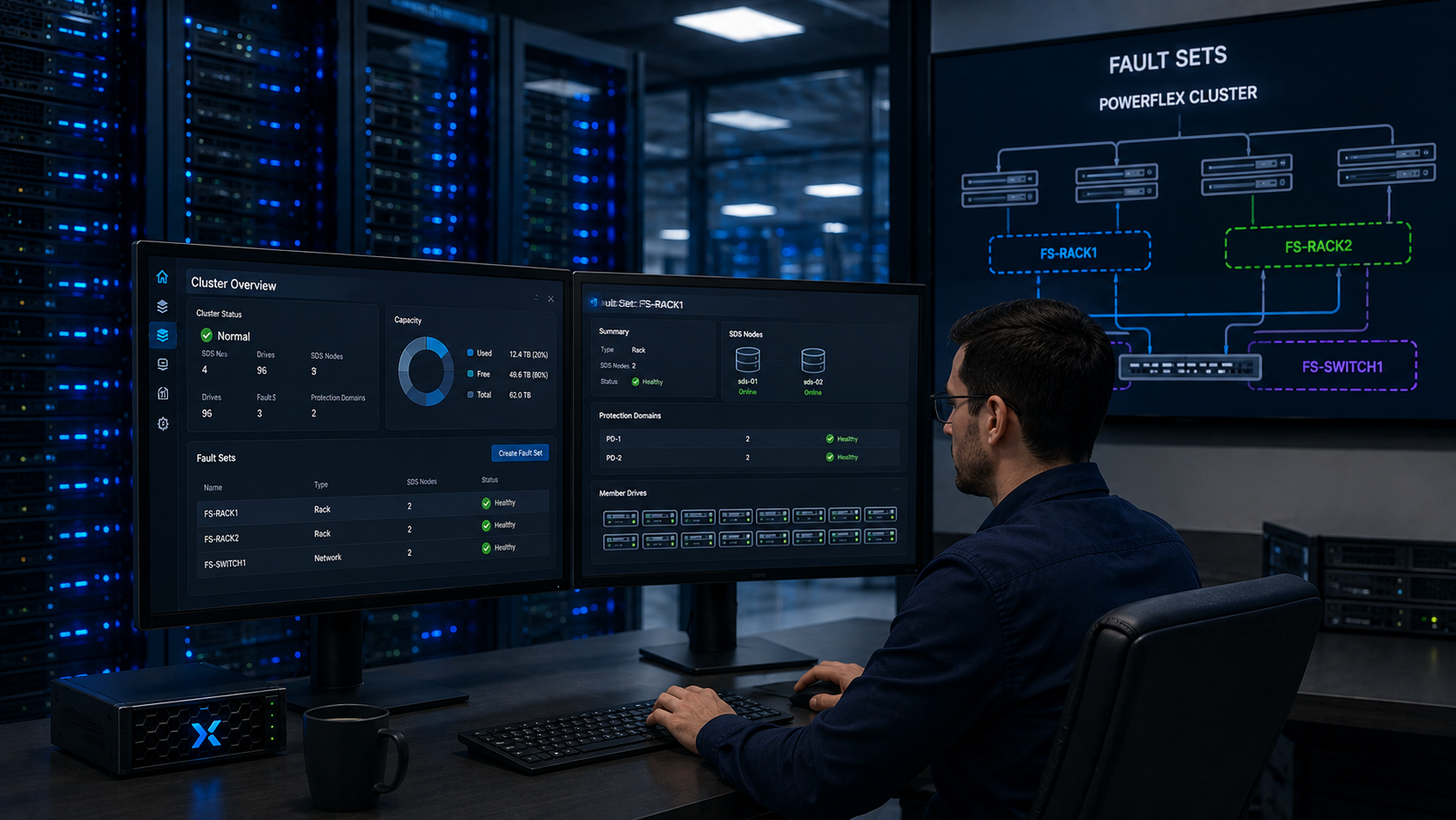
Dell PowerFlex Fault Sets help reduce the impact of failures that may affect multiple Storage Data Servers (SDSs) at the same time. By grouping SDSs that share a failure domain – such as servers in the same rack – PowerFlex can place mirrored data outside that group.
This article explains how Fault Sets work and walks through a PowerFlex 4.5.2 software-only lab running on nested virtual machines. It also shows how to create Fault Sets, add SDS nodes and storage devices, and estimate the spare capacity required by the example topology. The capacity figures are theoretical; check the actual Storage Pool capacity in PowerFlex Manager before creating volumes.
If you are new to the platform, read Getting Started with Dell PowerFlex: Architecture and Key Components for an overview of the main PowerFlex components, including the MDM, SDS, and SDC.
What are Fault Sets?
A Fault Set is a logical group of SDSs within a Protection Domain that are likely to become unavailable together. A typical example is a set of servers installed in the same rack or sharing another infrastructure failure domain.
PowerFlex stores each data piece in two copies on different fault units. A fault unit is either a named Fault Set or an SDS that is not assigned to a Fault Set. When Fault Sets are used, PowerFlex places the mirror for data in a Fault Set on SDSs outside that same Fault Set.
For mirroring, the system needs enough capacity across at least three fault units. This does not mean that every Protection Domain must always contain three named Fault Set objects: an unassigned SDS is treated as its own fault unit.
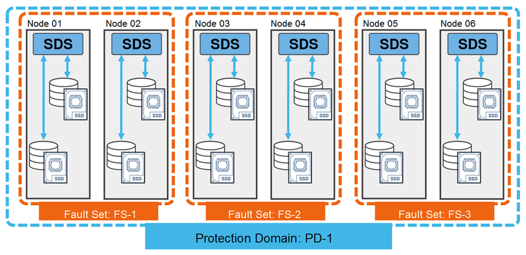
In this lab, the design uses three named Fault Sets, and each one contains two SDS nodes. The two-SDS membership is a property of this lab design, not a universal minimum for every PowerFlex Fault Set:
How do Fault Sets work?
PowerFlex distributes two copies of each data piece across different fault units. When a Fault Set is configured correctly, the mirror for its data is stored on SDSs outside that Fault Set. This design is intended to preserve data availability if all servers in one Fault Set fail at the same time.
This protection statement applies to the loss of one Fault Set under the documented topology. It is not an unconditional guarantee for simultaneous failures in multiple fault units, insufficient spare capacity, or other faults that make both copies inaccessible. PowerFlex automatically initiates rebuild activity after it detects a server, device, or network failure, but the process can take time and its completion depends on the system’s available capacity and state.
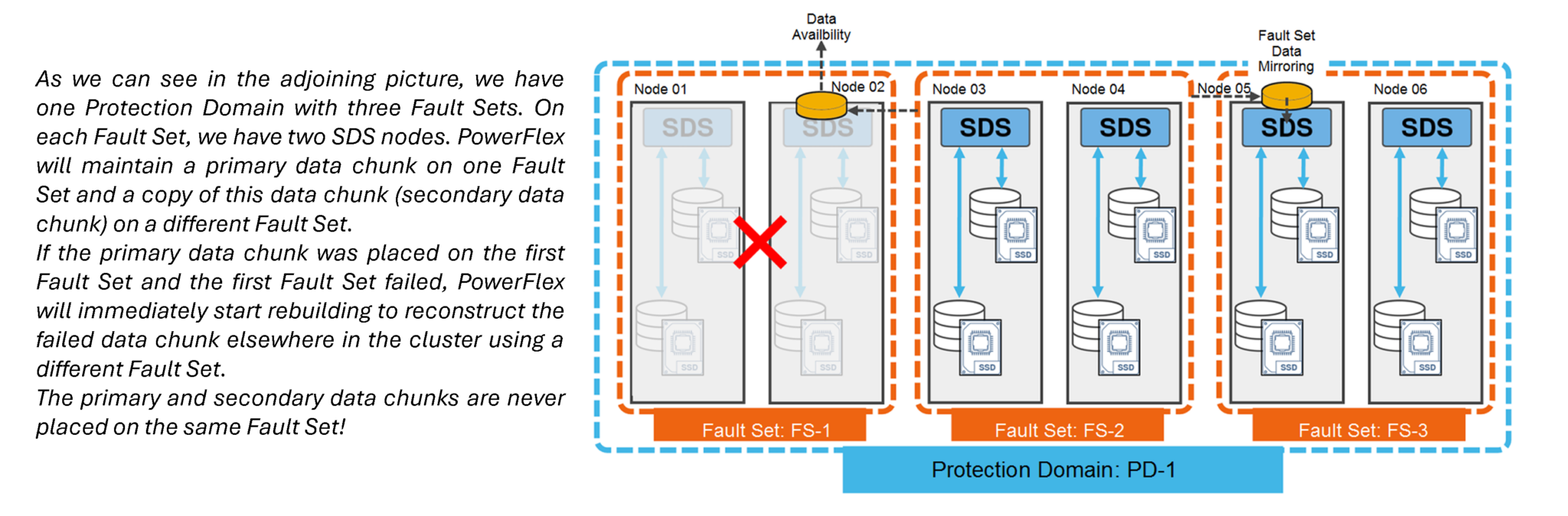
Mirroring Fault Set data ensures that another data copy is always available even if all the servers within the defined Fault Set fail simultaneously!
How can I create Fault Sets?
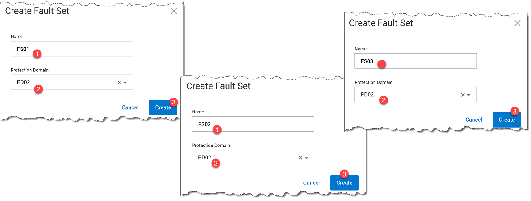
1- To create a Fault Set, access the PowerFlex Manager UI –> Block –> Fault Sets –> + Create Fault Set:
In this example, we will create three Fault Sets (FS01, FS02, and FS03):
2- Copy the SDS package to the SDS node and install it (Since we are using SLES 15 SP4, we chose the package for it):
MDM_IP="192.168.155.254,192.168.156.254" rpm -iv EMC-ScaleIO-sds-4.5-2100.105.sles15.4.x86_64.rpm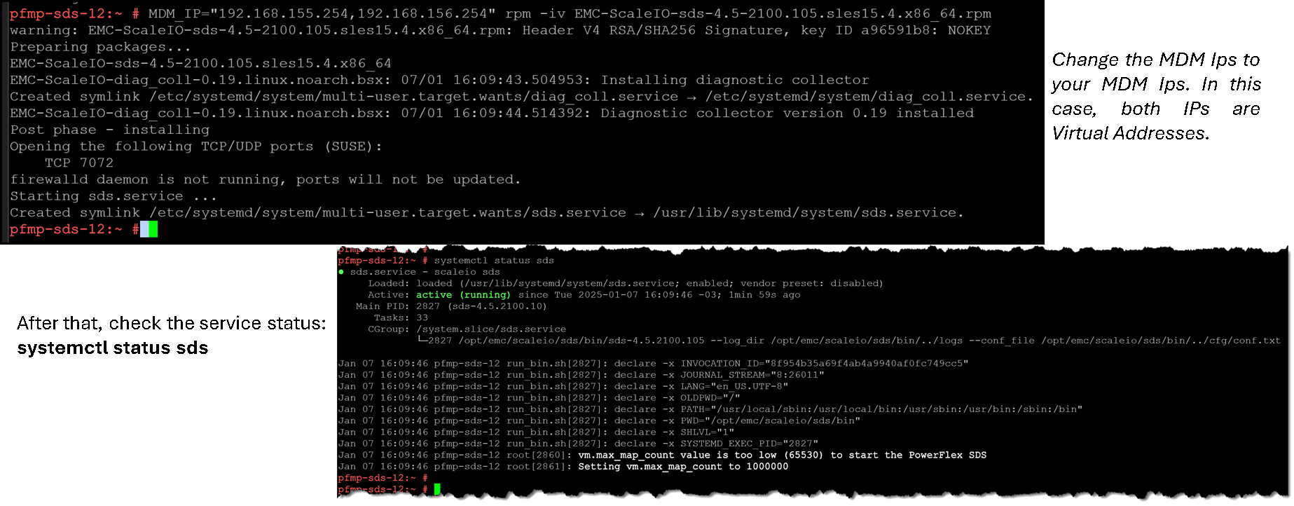
Note: Install the SDS package on all SDS nodes you want to be part of Fault Sets!
3- To add an SDS node to a Fault Set, access the PowerFlex Manager UI –> Block –> SDSs –> + Add SDS:
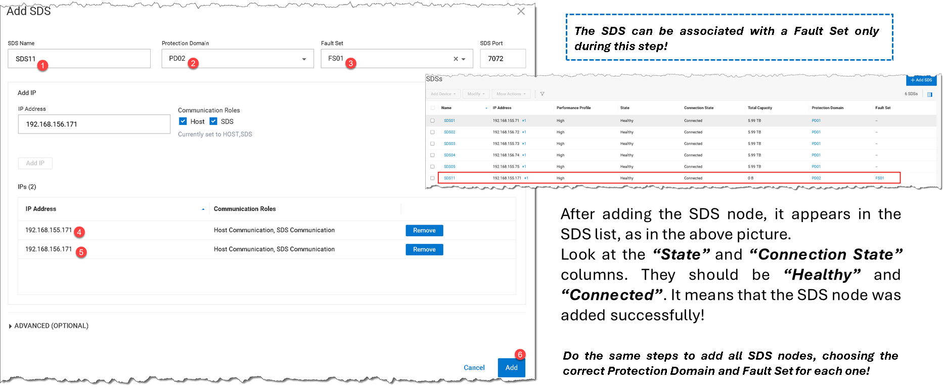
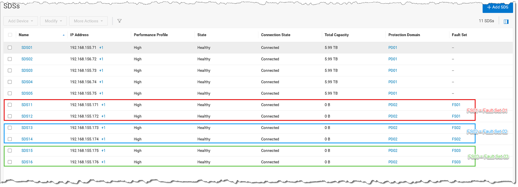
4- The result is three Fault Sets with two SDS nodes each, as we can see in the following picture:
5- For each SDS node, we have one disk device. Currently, the Storage Pool has no capacity because we do not add the disk devices (we only add the SDS node). The next step is to add each disk device. On the SDSs menu, select the SDS –> Add Device –> Storage Device:
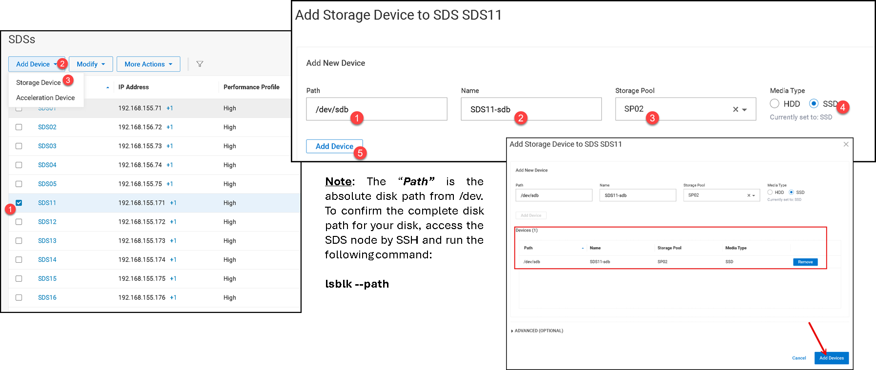
6- Afterward, go to the Devices menu to see the added device. On the PowerFlex Manager UI –> Block –> Devices:
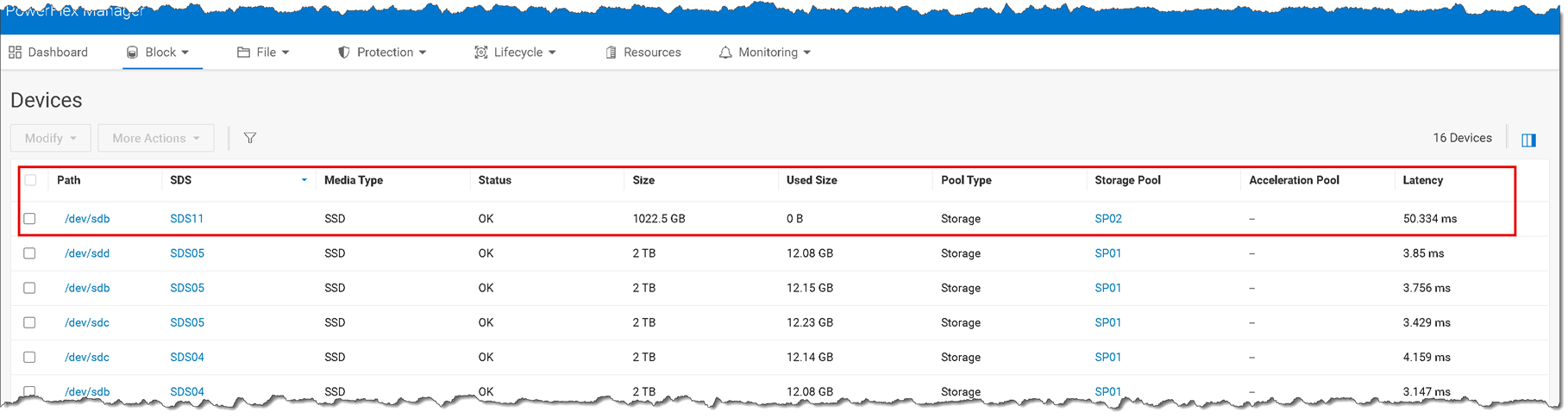
Do the same steps to add the other disk devices!
7- After adding all device disks, the Storage Pool “SP02” has the available capacity for using:

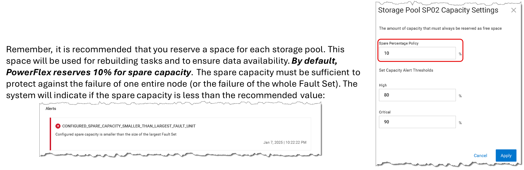
8- To set up the recommended spare capacity percentage, we can use the following calc:
- 100% divided by the number of SDS nodes or number of Fault Sets (if you are using Fault Sets)
- 100% divided by 3 (number of Fault Sets) = ~ 33%
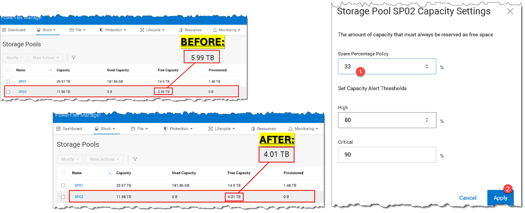
Deeping Dive about Raw and Free Space with Fault Sets
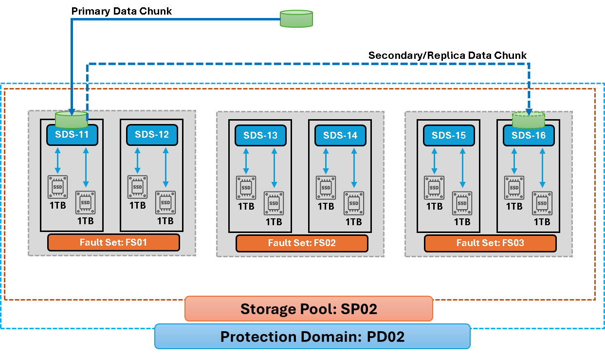
The following diagram shows our scenario using Fault Sets. We have three Fault Sets (FS01, FS02, and FS03), each with two SDS nodes. Looking inside each Fault Set, we have 2TB of raw capacity. However, since PowerFlex places each data chunk in a mesh-mirror way, it results in 1TB of usable/free capacity (PowerFlex automatically reserves 50% of the raw capacity to store the replica of each data chunk). So, based on this scenario:
1) What is the total usable/free capacity for the PowerFlex Cluster?
2) How do we calculate the spare capacity percentage for this PowerFlex Cluster?
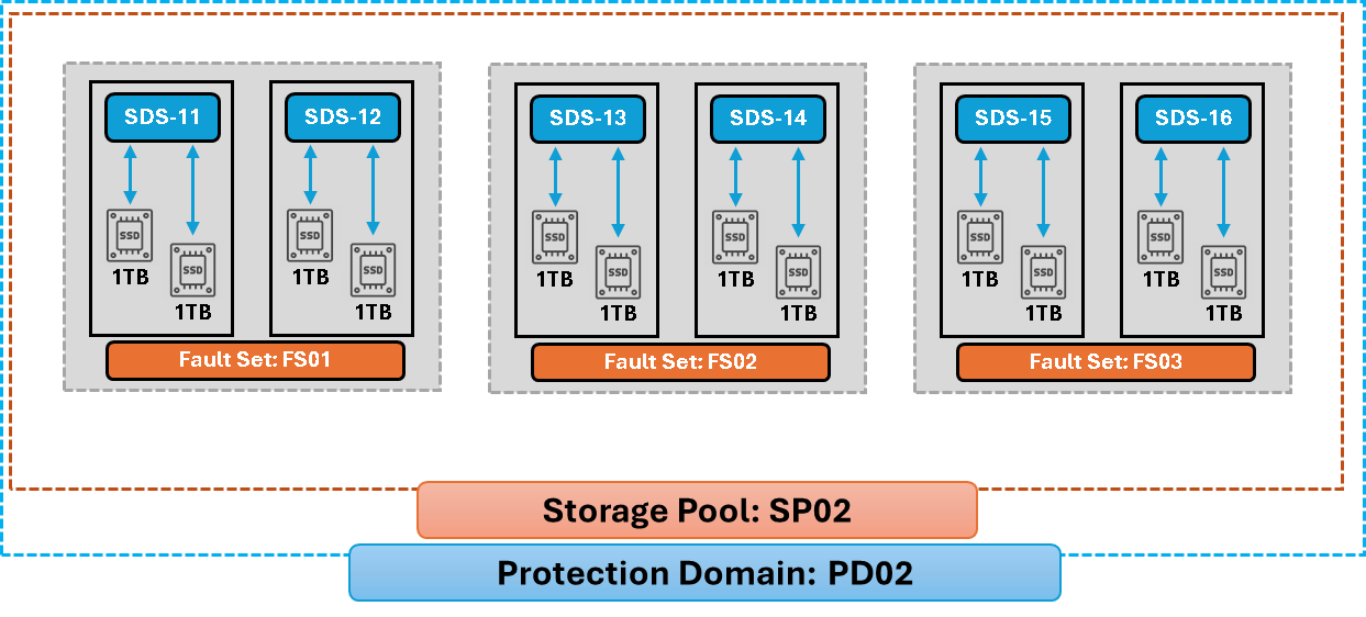
Answers:
1- FS01 (4TB) + FS02 (4TB) + FS03 (4TB) = 12TB of raw capacity
12TB – 50% of mirror-mesh overhead = 6TB of usable/free capacity

2- By default, 10% of spare capacity is reserved for each Storage Pool. However, to set up the correct value based on the number of SDS nodes/Fault Sets, we need:

100% / number of SDS nodes or Fault Sets

100% / 3 Fault Sets = ~ 33% of spare capacity
6TB – 33% = ~ 4TB of usable/free capacity
How a data chunk is placed within Fault Sets?
PowerFlex stores each data piece in two copies on different fault units. When a Fault Set is used as a failure domain, the mirror for data in that Fault Set is placed on SDSs outside it. The copies are distributed by PowerFlex’s placement algorithm; this diagram illustrates the cross-fault-unit principle rather than a fixed mapping between specific Fault Set names:
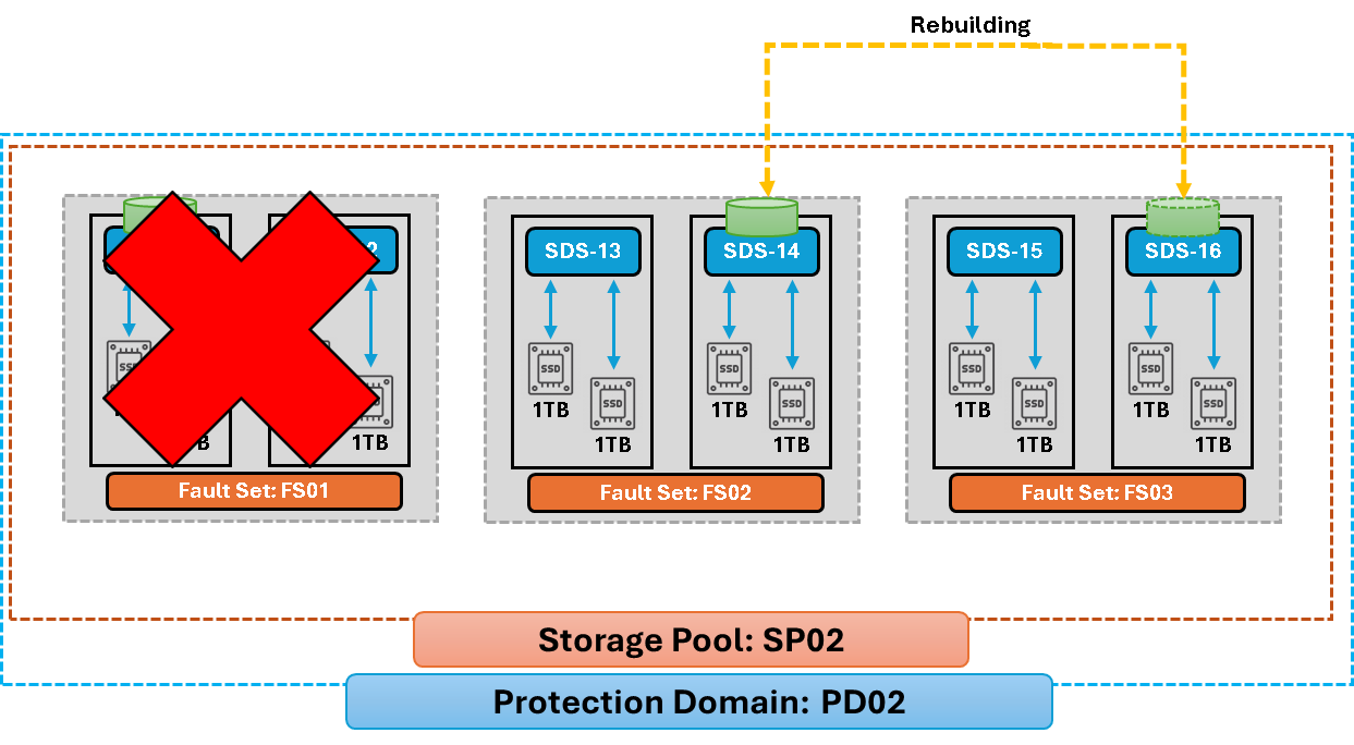
When PowerFlex detects a server, device, or network failure, it automatically initiates a rebuild process to protect the affected data. PowerFlex selects the rebuild type. A forward rebuild creates a replacement copy on another server, while a backward rebuild resynchronizes a copy that has returned.
“Automatically initiates” does not mean that the rebuild finishes immediately. The work can take time, and the pool’s available capacity, spare policy, rebuild settings, and system state affect the recovery. Monitor the Storage Pool and rebuild status in PowerFlex Manager until the relevant activity has completed and the system is healthy:
For a broader example of a nested PowerFlex 4.5.2 deployment, see Deploying a New PowerFlex Cluster. That article covers the cluster deployment workflow; the Fault Set configuration and capacity calculations in this guide are specific to the topology shown here.
Design the Failure Domains, Then Verify the Reserve
Fault Sets make PowerFlex’s protection domains explicit by grouping SDSs that may fail together. In this lab, the important checks are that the SDSs are assigned to the intended Fault Sets, devices are added to the correct Storage Pool, and the spare reserve is sized for the largest failure unit.
The capacity example is theoretical, so confirm the actual raw and free-net-capacity values in PowerFlex Manager. For production systems, validate the supported software and operating-system combination and follow Dell’s guidance for the exact PowerFlex release and topology.
To add capacity to existing SDS nodes rather than build a Fault Set topology, see Expanding the PowerFlex Cluster with New Disks. That walkthrough covers adding available devices to an existing Storage Pool; the procedure is different from assigning SDSs to Fault Sets.
External References
- Dell — PowerFlex 4.5.x Technical Overview: Fault Sets Defines Fault Sets and fault units, explains why mirrored data is placed outside its Fault Set, and states the minimum three-fault-unit requirement for mirroring.
- Dell — PowerFlex 4.5.x Administration Guide: Fault Sets Describes the Fault Set failure-domain model and the placement of mirrored chunks outside the originating Fault Set, including the documented protection for one Fault Set failure.
- Dell — Add Fault Sets Documents the PowerFlex Manager workflow for creating Fault Sets, the prerequisites, and the requirement to assign an SDS to a Fault Set during SDS creation.
- Dell — Add Storage Data Servers Lists the SDS creation fields in PowerFlex Manager, including Protection Domain, Fault Set, communication port, and IP addresses.
- Dell — Add Storage Devices Explains how to add devices to an SDS and Storage Pool, the media-type prerequisites, default device tests, and the warning that a takeover can erase existing data.
- Dell — PowerFlex CLI Reference: System Limits Lists core system limits, including up to 64 Fault Sets per Protection Domain and up to 64 SDSs per Fault Set; PowerFlex Manager workflows may have lower operation-specific limits.
- Dell — Protection and Load Balancing Explains the two-copy distributed mesh-mirrored layout and how PowerFlex distributes copies across different fault units.
- Dell — Modify Spare Policy Documents the 10% default, the spare-percentage setting as a portion of total capacity, the equal-SDS guidance, and the reserve needed for the largest node or Fault Set.
- Dell — Set Spare Capacity for a Medium-Granularity Storage Pool Provides the PowerFlex 4.5.x spare-capacity configuration procedure and an example that rounds a three-node cluster reserve up to 34%.
- Dell — Rebuild Describes automatic rebuild initiation after a detected failure, the difference between forward and backward rebuild, and how PowerFlex selects the rebuild type.
- Dell — PowerFlex Operating-System Support Matrix Maps operating-system releases to PowerFlex versions and components. Check the exact build and component combination, including SLES 15 SP4 and SDS(MG), before deployment.
