

Expanding a Dell PowerFlex MDM cluster from three nodes to five can improve the resilience of the MDM control plane. The transition depends on installing each new MDM with the correct role before adding it to the existing cluster. This walkthrough covers the supported workflow for a healthy PowerFlex 4.5.2 three-node cluster in a lab running SUSE Linux Enterprise Server (SLES) 15 SP4. In this example, pfmp-sds-04 is the additional manager MDM and pfmp-sds-05 is the additional tie-breaker.
Important: Dell defines an MDM’s manager or tie-breaker role during installation. If a node was installed with the wrong role, stop and reinstall its MDM package using the applicable Dell procedure. Do not change conf.txt, delete or recreate the MDM service manually, or use --force_clean as a role-conversion method. The example commands below use lab IP addresses; replace them with the correct addresses, names, and interface configuration for your environment.
If you are new to PowerFlex or want a refresher on the roles used in this procedure, see Getting Started with Dell PowerFlex: Architecture and Key Components, which explains the platform’s core components and architecture.
Understand the Five-Node MDM Layout
A five-node MDM cluster contains one primary MDM, two secondary manager MDMs, and two tie-breakers. Manager MDMs hold replicas of the MDM repository; tie-breakers participate in primary-MDM elections but are not managers. This change affects MDM-cluster availability. It does not replace storage-side redundancy or guarantee that all PowerFlex components are fault tolerant.
Before proceeding, confirm that the existing cluster is healthy and that both target servers are new MDM nodes—not active or connected cluster members. Confirm that the MDM package release is supported for the installed PowerFlex version and that all MDM cluster members use the same MDM package. An rpm -qa listing shows installed package names and versions, but it does not by itself prove that the complete package set matches the applicable Dell release catalog.
For additional SCLI examples—including how to inspect MDM roles, cluster mode, and cluster state—see PowerFlex SCLI Command Guide: Monitor and Manage Your Cluster.
Check the Current MDM Cluster
Currently, our MDM cluster has three nodes, as we can see below:
scli --query_cluster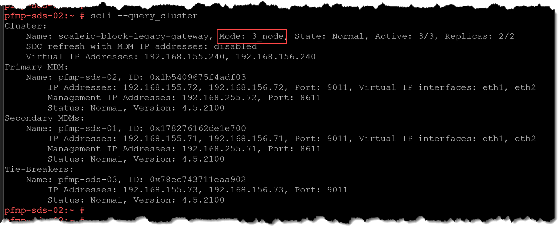
Record the current primary, secondary, tie-breaker, cluster mode, and state. Do not continue unless the cluster is healthy and reports the expected three-node topology. Use the actual MDM names returned by this command in later steps.
Confirm the New MDM Roles
The two new nodes must have these roles before they are added as standbys:
pfmp-sds-04: manager, which can become a secondary MDM.pfmp-sds-05: tie-breaker, which participates in primary-MDM elections.
Both nodes (pfmp-sds-04 and pfmp-sds-05) already have the necessary rpm packages installed:
pfmp-sds-04:~ # rpm -qa | grep -i EMC
EMC-ScaleIO-lia-4.5-2100.105.sles15.4.x86_64
EMC-ScaleIO-activemq-5.18.3-68.noarch
EMC-ScaleIO-sds-4.5-2100.105.sles15.4.x86_64
EMC-ScaleIO-mdm-4.5-2100.105.sles15.4.x86_64

pfmp-sds-05:~ # rpm -qa | grep -i EMC
EMC-ScaleIO-lia-4.5-2100.105.sles15.4.x86_64
EMC-ScaleIO-activemq-5.18.3-68.noarch
EMC-ScaleIO-sds-4.5-2100.105.sles15.4.x86_64
EMC-ScaleIO-mdm-4.5-2100.105.sles15.4.x86_64
Dell documents that the role is selected during MDM installation and cannot be changed later without reinstalling the MDM. If the manager-add operation reports that pfmp-sds-04 is a tie-breaker, stop. Reinstall the MDM on that new node through the applicable PowerFlex 4.5.2 and SLES procedure, selecting the manager role. Do not follow the unsupported conf.txt edit or service deletion/recreation described in the original draft.
For PowerFlex systems managed by PowerFlex Manager, check Dell’s release-specific prerequisites for adding a standby MDM. Depending on the deployment, certificate preparation may be required before running SCLI.
Add the Manager as a Standby MDM
After confirming that pfmp-sds-04 was installed as a manager, add it as a standby manager from the current primary MDM. The following command uses the lab addresses from this example:
scli --add_standby_mdm --new_mdm_ip 192.168.155.74,192.168.156.74 --mdm_role manager --new_mdm_management_ip 192.168.255.74 --new_mdm_virtual_ip_interface eth1,eth2After executing the command, we had an error:

“Error: MDM failed command. Status: MDM role is not a Secondary but a Tie-Breaker”
In this case, the error means that the MDM node cannot be a manager (Secondary) node.
So, to fix this error, we need to access the node to be added (pfmp-sds-04) and execute the following steps:
1. Edit the file “/opt/emc/scaleio/mdm/cfg/conf.txt” and change the following line:
FROM:
actor_role_is_manager=0
TO:
actor_role_is_manager=1
2. Delete and recreate the MDM service:
/opt/emc/scaleio/mdm/bin/delete_service.sh
/opt/emc/scaleio/mdm/bin/create_service.sh
3. Check the MDM service status – it must be running:
systemctl status mdmAfterward, try to add the manager node again:
scli --add_standby_mdm --new_mdm_ip 192.168.155.74,192.168.156.74 --mdm_role manager --new_mdm_management_ip 192.168.255.74 --new_mdm_virtual_ip_interface eth1,eth2 --new_mdm_name pfmp-sds-04 --force_clean --i_am_sureAs shown, the node has been added successfully with the manager role:

Checking the cluster, we can now see the added node in the Standby MDM section:
scli --query_cluster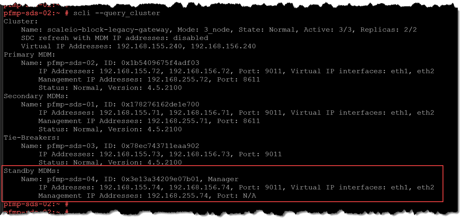
Add the Tie-Breaker as a Standby MDM
After confirming that pfmp-sds-05 was installed as a tie-breaker, add it as a standby:
scli --add_standby_mdm --new_mdm_ip 192.168.155.75,192.168.156.75 --mdm_role tb --new_mdm_management_ip 192.168.255.75 --new_mdm_name pfmp-sds-05 --force_clean --i_am_sure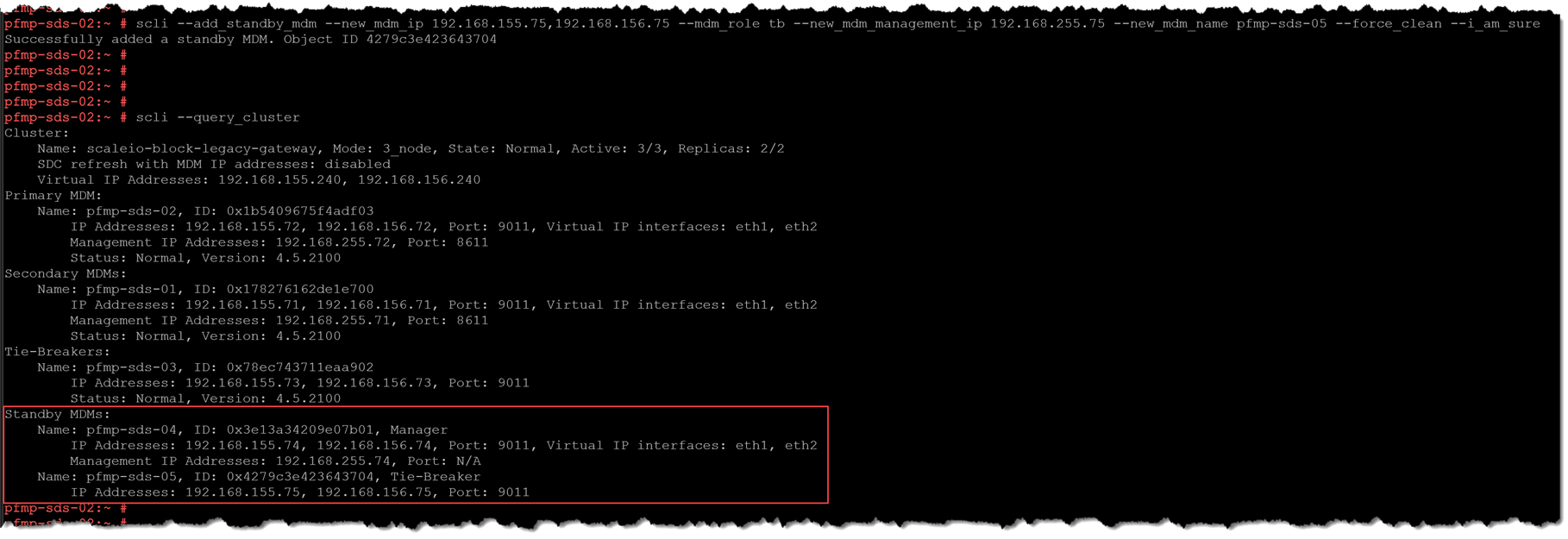
Use the actual network details for your environment. Do not run standby-add procedures against an active or connected Manager MDM. Dell warns that using the standby procedure on an active or connected Manager MDM can cause data unavailability or data loss.
Verify Both Standby MDMs
Query the cluster again:
scli --query_clusterVerify that both new nodes appear as standby MDMs with the intended roles and normal state. If a node has the wrong role, is missing, or reports an unexpected state, stop and resolve that issue before changing the cluster mode. The mode-switch command does not repair an incorrectly installed role.
Switch the Cluster to Five-Node Mode
Only after both new nodes are correctly installed and verified as standbys, run the mode switch on the current primary MDM:
scli --switch_cluster_mode --cluster_mode 5_node --add_secondary_mdm_name pfmp-sds-04 --add_tb_name pfmp-sds-05As shown, the switchover process has been executed successfully. Now, our MDM cluster is a five-node cluster:
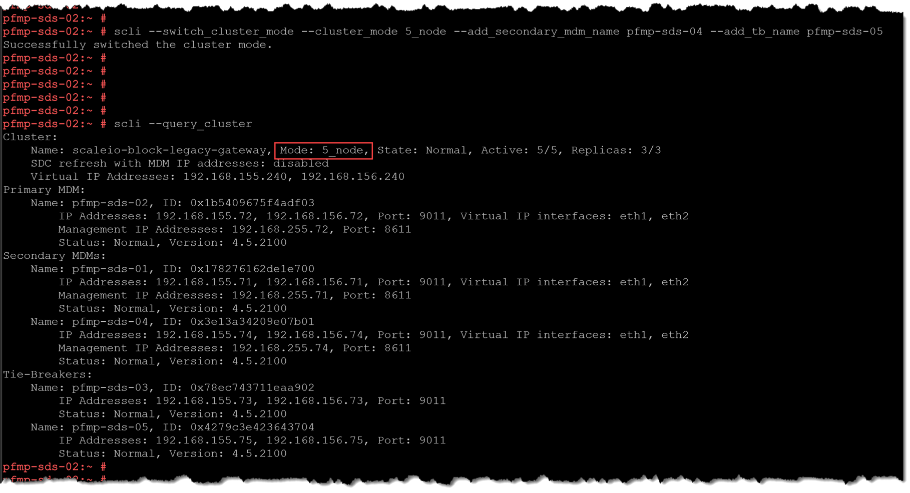
This change cannot be replicated in the PowerFlex Manager UI immediately. On the Resources page, we continue to see a three-node cluster:
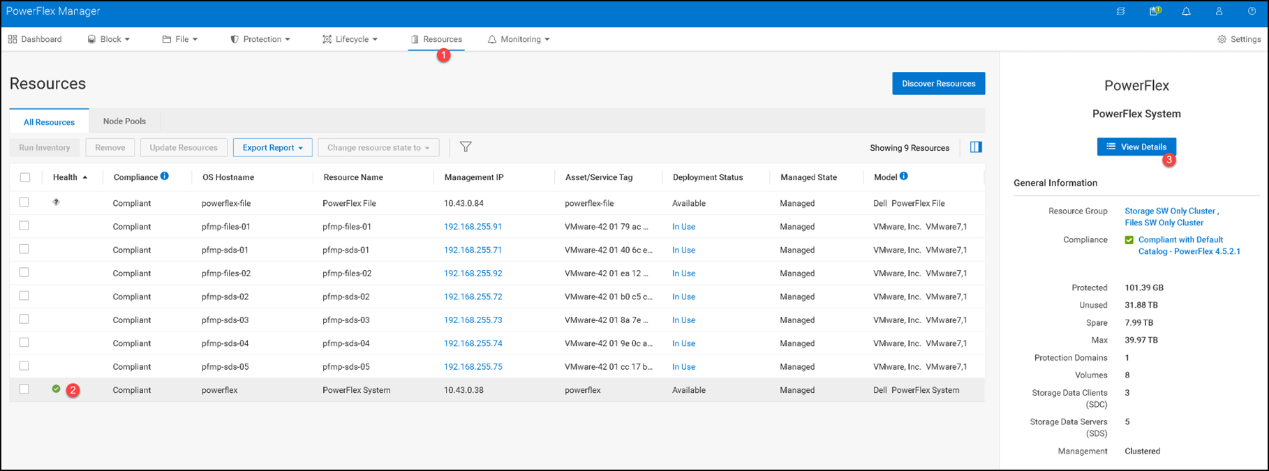
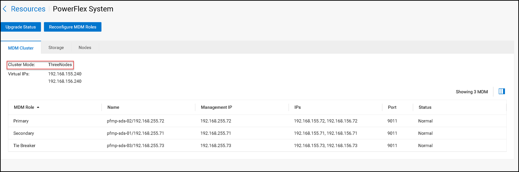
Confirm that the cluster reports 5_node, a normal state, and the expected primary, secondary MDMs, and tie-breakers.
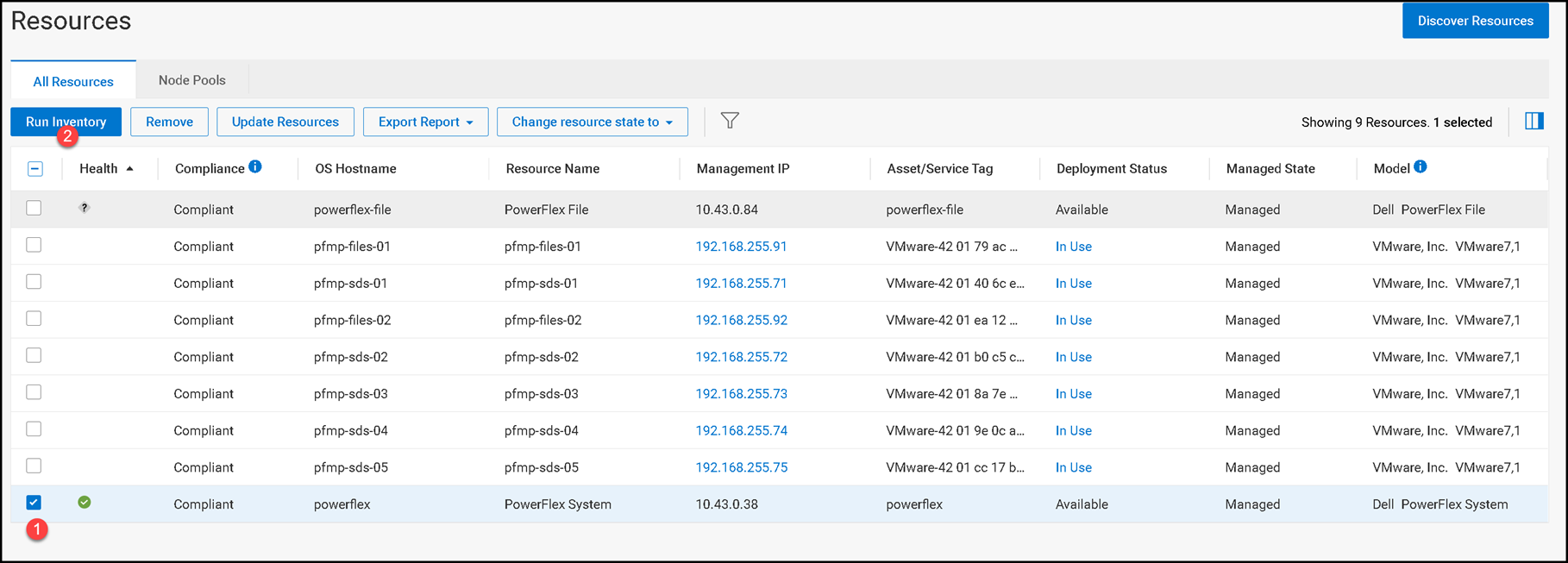
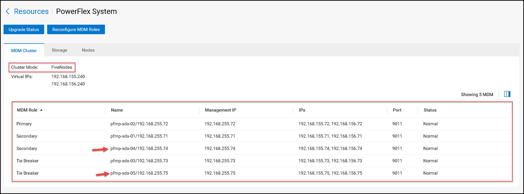
Because the topology change was made outside PowerFlex Manager, refresh its inventory. In Resources > All Resources, select the PowerFlex resource and click Run Inventory. Wait for the resource to finish its inventory operation and return to an available state. If the resource group must also reflect the new nodes, open Lifecycle > Resource Groups, select the relevant resource group, and choose More Actions > Update Resource Group Details. Review the inventory summary and finish the update.
Dell documents these steps for reflecting external changes and newly added nodes. Do not assume that a single inventory run guarantees an immediate update to every MDM-specific view in the interface. If a view remains stale, verify the inventory and resource-group status before repeating any SCLI change.
Keep MDM Roles and Inventory in Sync
The key to a safe three-to-five-node transition is to install each new MDM with its intended role, add both nodes as standbys, and verify their state before switching cluster mode.
Afterward, reconcile the external change in PowerFlex Manager using its documented inventory and resource-group update workflow.
External References
- Dell PowerFlex 4.5.x — Create a Five-Node MDM Cluster Official installation guide describing how to add manager and tie-breaker MDMs as standbys, switch to five-node mode, and verify the resulting cluster topology.
- Dell PowerFlex 4.5.x CLI Reference — add_standby_mdm Documents the SCLI syntax and parameters for adding a standby manager or tie-breaker MDM, including the meaning of the role and cleanup options.
- Dell PowerFlex 4.5.x CLI Reference — switch_cluster_mode Provides the supported syntax for changing MDM cluster mode and adding secondary MDMs or tie-breakers. It also explains that –i_am_sure skips execution safety prompts.
- Dell PowerFlex 4.5.x Technical Overview — MDM Cluster Explains the primary, secondary, manager, standby, and tie-breaker roles, including that an MDM role is selected during installation and cannot be changed later without reinstalling the MDM.
- Dell KB 000215132 — Add a Standby Manager MDM to PowerFlex 4.x Lists prerequisites for adding a new standby MDM to a PowerFlex Manager-managed system and warns not to run the standby procedure against an active or connected Manager MDM.
- Dell PowerFlex Operating System Support Matrix Lists operating-system and PowerFlex component support combinations, including SLES 15 SP4 and applicable PowerFlex 4.5 releases. Confirm the complete release and package combination before deployment.
- Dell PowerFlex 4.5.x Administration Guide — Managing External Changes Describes when to run inventory and update resource-group details after nodes or other resources have been added outside PowerFlex Manager.
- Dell PowerFlex 4.5.x Administration Guide — Update Resource-Group Details Provides the PowerFlex Manager workflow for rediscovering a resource group and reviewing externally added or removed components.
