
VMware NSX overlay networking uses Tunnel Endpoints (TEPs) to carry Geneve-encapsulated traffic between transport nodes. ESXi hosts and NSX Edge nodes need reliable IP connectivity across the underlay network for these overlay tunnels to remain healthy.
When overlay traffic fails, one of the first checks is to verify TEP-to-TEP connectivity, MTU, and the tunnel path from both the ESXi host and the Edge node.
In this lab, I will show the commands I use to validate that path from both sides.
Let’s Look Inside an Edge-VM
In the below picture, we can see a diagram showing the details of the Edge-VM.
As we can see, the Edge-VM has some interfaces, and all interfaces are connected to an internal N-VDS. Basically:
- mgmt interface: Each Edge- VM has a management interface just for management traffic;
- fp-ethX interfaces: NSX Edge nodes use fast-path interfaces such as
fp-eth0,fp-eth1, and others for dataplane connectivity. Depending on the Edge design and uplink mapping, these interfaces back the host switches used for overlay TEP connectivity, VLAN uplinks, or other dataplane functions. - The TEP itself is the tunnel endpoint IP used by the NSX overlay dataplane. Therefore, an
fp-ethXinterface should not automatically be described as “the TEP” without checking how that Edge node is configured.
Additionally, these interfaces can be connected to a vSphere Standard Switch or can be connected to a vSphere Distributed Switch, as we can see in the below picture:
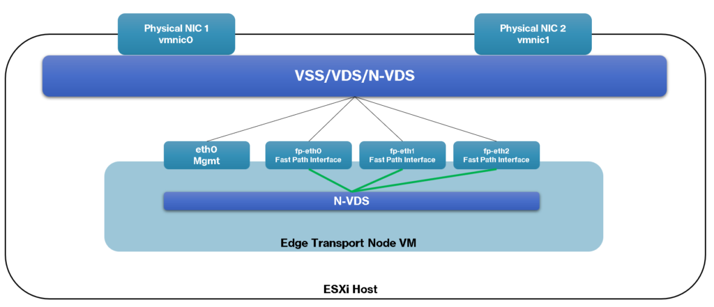
Note: This diagram represents the lab architecture used when this article was originally created. NSX host-switch and Edge networking designs can differ between NSX and vSphere releases.
As we commented before, the Edge-VM is responsible for hosting the Tier-0 and/or the Tier-1 gateway:
- Tier-0 gateway: This gateway provides “North-South” connectivity. In a single-tier topology, the Tier-0 gateway also provides “East-West” connectivity;
- Tier-1 gateway: This gateway provides “East-West” connectivity.
About the traffic direction:
- North-South: When we talk about the “North-South” traffic, we are talking about the traffic between the virtual environment with the physical environment. In this context, the traffic between the NSX-T environment with the physical network or with the outside environment to the NSX-T.
- East-West: This traffic refers to the traffic between VMs inside the NSX-T environment. For example, when one VM needs to communicate with another VM using the NSX-T environment, this traffic can be considered “East-West” traffic.
TEP Interface
Each Transport Node Device on the NSX-T architecture has an interface called the TEP interface (Tunnel EndPoint Interface).
This interface is dedicated to each device communicating with each other on the Overlay network. So, based on it, each Host (ESXi, for example) and each Edge-VM has a TEP interface. If we have problems on this network, certainly we have problems with the workload running inside the NSX-T environment.
We will show some steps for testing the communication on this network.
Because of that, it’s very important to know if each Transport Node Device can reach the other on this Overlay Network!
Testing the Overlay Networking from the ESXi host
In this example, we will perform these tests from an ESXi host present on the cluster – This ESXi host, of course, was prepared to be part of the NSX-T architecture:
1) Accessing the ESXi host by SSH and Listing the VMkernel interfaces:
esxcfg-vmknic -lExample:
[root@vhost01:~] esxcfg-vmknic -l
Interface  Port Group/DVPort/Opaque Network        IP Family IP Address                              Netmask         Broadcast       MAC Address       MTU     TSO MSS   Enabled Type                NetStack
vmk0       2                                       IPv4      192.168.255.11                          255.255.255.0   192.168.255.255 00:0c:29:39:e1:6d 1500    65535     true    STATIC              defaultTcpipStack
vmk1       26                                      IPv4      192.168.254.11                          255.255.255.0   192.168.254.255 00:50:56:6c:54:a6 1500    65535     true    STATIC              defaultTcpipStack
vmk3       42                                      IPv4      192.168.200.11                          255.255.255.0   192.168.200.255 00:50:56:6c:fd:90 1500    65535     true    STATIC              defaultTcpipStack
vmk4       50                                      IPv4      192.168.200.111                         255.255.255.0   192.168.200.255 00:50:56:65:c5:6b 1500    65535     true    STATIC              defaultTcpipStack
vmk10      5d032e0a-7ca3-417e-8c72-c2e8f4973ed3    IPv4      192.168.250.3                           255.255.255.0   192.168.250.255 00:50:56:61:b0:49 1700    65535     true    STATIC              vxlan
vmk50      60f9d0dd-740e-43da-b39f-c1190adbbc49    IPv4      169.254.1.1                             255.255.0.0     169.254.255.255 00:50:56:61:ce:2d 1700    65535     true    STATIC              hyperbus
vmk2       34                                      IPv4      192.168.253.11                          255.255.255.0   192.168.253.255 00:50:56:6a:12:bf 1700    65535     true    STATIC              vmotion
Here, we can apply a filter just to filter the VMkernel interface that has the type “vxlan”:
esxcfg-vmknic -l | grep vxlanExample:
[root@vhost01:~] esxcfg-vmknic -l | grep vxlan
vmk10      5d032e0a-7ca3-417e-8c72-c2e8f4973ed3    IPv4      192.168.250.3                           255.255.255.0   192.168.250.255 00:50:56:61:b0:49 1700    65535     true    STATIC              vxlan
2) Starting ping test from the ESXi host to another device in the Overlay network:
vmkping -S vxlan 192.168.250.4 -s 1572 -d -c 5-S vxlan
Use the NSX overlay TCP/IP stack. Depending on the NSX/ESXi
version, this stack may still be displayed as “vxlan” even though
NSX overlay traffic uses Geneve encapsulation.
192.168.250.4
Destination TEP IP address.
-s 1572
Set the ICMP payload to 1572 bytes. With a 20-byte IPv4 header
and an 8-byte ICMP header, this produces a 1600-byte IP packet.
-d
Set the Don’t Fragment bit.
-c 5
Send five ICMP echo requests.
Example:
[root@vhost01:~] vmkping -S vxlan 192.168.250.4 -s 1572 -d -c 5
PING 192.168.250.4 (192.168.250.4): 1572 data bytes
1580 bytes from 192.168.250.4: icmp_seq=0 ttl=64 time=4.757 ms
1580 bytes from 192.168.250.4: icmp_seq=1 ttl=64 time=0.810 ms
1580 bytes from 192.168.250.4: icmp_seq=2 ttl=64 time=0.570 ms
1580 bytes from 192.168.250.4: icmp_seq=3 ttl=64 time=0.558 ms
1580 bytes from 192.168.250.4: icmp_seq=4 ttl=64 time=0.627 ms

--- 192.168.250.4 ping statistics ---
5 packets transmitted, 5 packets received, 0% packet loss
round-trip min/avg/max = 0.558/1.464/4.757 ms
NSX overlay traffic requires an underlay MTU of at least 1600 bytes. Broadcom currently recommends a larger value, such as 1700 or jumbo MTU, when supported consistently across the physical network.
If the issue appears to involve physical NIC drops, virtual switch counters, or a specific VM datapath rather than the TEP itself, see “How to Troubleshoot Packet Drops on an ESXi Host“.
Testing the Overlay Networking from the Edge-VM
In this example, we will perform these tests from an Edge-VM deployed on our lab environment:
1) Accessing the Edge-VM by SSH (with admin user) and Listing the Logical Routing running on this Edge-VM:
get logical-routerExample:
edge-01> get logical-router
Tue Oct 17 2023 UTC 15:33:31.803
Logical Router
UUID                                   VRF    LR-ID  Name                              Type                        Ports   Neighbors
736a80e3-23f6-5a2d-81d6-bbefb2786666   0      0                                        TUNNEL                      3       2/5000
a717c250-ec04-4ee2-bae8-002206706a23   1      1025   SR-t1-gw-prd                      SERVICE_ROUTER_TIER1        5       2/50000
7a1279af-f686-48af-9969-089d38549dd3   2      2063   SR-t0-gw                          SERVICE_ROUTER_TIER0        5       3/50000
e6c82381-78e7-44f4-bbc1-56b0e416cf8a   4      1      DR-t1-gw-prd                      DISTRIBUTED_ROUTER_TIER1    6       0/50000
5c92f7a6-2a74-48a6-bb21-8da1be513813   5      11     DR-t0-gw                          DISTRIBUTED_ROUTER_TIER0    6       0/50000
2cc41bf1-91d8-4f7b-9349-ce62cbe1070a   6      1026   SR-t1-gw-devqa                    SERVICE_ROUTER_TIER1        5       2/50000
cc39cfdc-624c-438d-a038-c0adac11866b   7      2      DR-t1-gw-devqa                    DISTRIBUTED_ROUTER_TIER1    6       0/50000
2) Identify the VRF ID associated with the TUNNEL logical router. This is the routing context used for the Edge TEP connectivity test;
3) Using the TUNNEL UUID, we can see details of the forwarding table:
get logical-router 736a80e3-23f6-5a2d-81d6-bbefb2786666 forwardingNote: In this example, the “736a80e3-23f6-5a2d-81d6-bbefb2786666” is the UUID of the TUNNEL Logical Router.
Example:
edge-01> get logical-router 736a80e3-23f6-5a2d-81d6-bbefb2786666 forwarding
Tue Oct 17 2023 UTC 15:36:09.633
Logical Router
UUID                                   VRF    LR-ID  Name                              Type
736a80e3-23f6-5a2d-81d6-bbefb2786666   0      0                                        TUNNEL
IPv4 Forwarding Table
IP Prefix          Gateway IP                                Type        UUID                                   Gateway MAC
192.168.250.0/24                                             route       fd27da66-d2e4-5eb7-b320-3e647fd1beca
192.168.250.4/32                                             route       8f6a05bd-e029-5be4-ac5f-d5a9f5823ca0
In this example, the IP 192.168.250.4/32 is the IP address of the TEP interface for the Edge-VM.
4) Additionally, we can see what neighbors the TUNNEL Logical Router has:
get logical-router 736a80e3-23f6-5a2d-81d6-bbefb2786666 neighborExample:
edge-01> get logical-router 736a80e3-23f6-5a2d-81d6-bbefb2786666 neighbor
Tue Oct 17 2023 UTC 15:37:38.177
Logical Router
UUID        : 736a80e3-23f6-5a2d-81d6-bbefb2786666
VRF         : 0
LR-ID       : 0
Name        :
Type        : TUNNEL
Neighbor
    Interface   : fd27da66-d2e4-5eb7-b320-3e647fd1beca
    IP          : 192.168.250.1
    MAC         : 00:50:56:67:d8:2d
    State       : reach
    Timeout     : 811

    Interface   : fd27da66-d2e4-5eb7-b320-3e647fd1beca
    IP          : 192.168.250.5
    MAC         : 00:50:56:a0:f0:07
    State       : reach
    Timeout     : 343
In this example, the TUNNEL Logical Router has two neighbors (IPs 192.168.250.1 and 192.168.250.5).
5) To perform a ping test from the TEP interface, we can do it according to the below command:
ping 192.168.250.1 source 192.168.250.4 vrfid 0 size 1572 dfbit enable repeat 5192.168.250.1
Target TEP IP
192.168.250.4
Source TEP IP
vrfid 0
VRF ID of the TUNNEL Logical Router
size 1572
Sets the ICMP payload used to validate a 1600-byte path without fragmentation.
dfbit enable
Sending the packet without fragmentation
repeat 5
Number of packets that will be sent
Example:
edge-01> ping 192.168.250.1 source 192.168.250.4 vrfid 0 size 1572 dfbit enable repeat 5
PING 192.168.250.1 (192.168.250.1) from 192.168.250.4: 1572 data bytes
1580 bytes from 192.168.250.1: icmp_seq=0 ttl=64 time=1.170 ms
1580 bytes from 192.168.250.1: icmp_seq=1 ttl=64 time=1.833 ms
1580 bytes from 192.168.250.1: icmp_seq=2 ttl=64 time=2.421 ms
1580 bytes from 192.168.250.1: icmp_seq=3 ttl=64 time=1.510 ms
1580 bytes from 192.168.250.1: icmp_seq=4 ttl=64 time=1.994 ms

--- 192.168.250.1 ping statistics ---
5 packets transmitted, 5 packets received, 0.0% packet loss
round-trip min/avg/max/stddev = 1.170/1.786/2.421/0.425 ms
Check the NSX TEP Tunnel State
On the ESXi host, check the BFD tunnel sessions:
nsxdp-cli bfd sessions listLook for the remote TEP and verify that the session state is:
upAlso check whether the sent and received counters are increasing.
A successful vmkping confirms IP reachability and MTU for the tested packet, but it does not prove that the NSX tunnel itself is healthy.
NSX overlay connectivity also depends on Geneve and BFD traffic. Current NSX deployments use:
UDP 6081  - Geneve
UDP 3784  - BFD control
UDP 4784  - BFD echo / multihop scenarios
Intermediate firewalls or physical network devices can therefore allow ICMP while still blocking the traffic required for overlay tunnels.
What to Check When TEP Connectivity Fails
If TEP-to-TEP connectivity fails, investigate:
- TEP IP configuration
- TEP VLAN
- Physical switch trunks
- Routing between Host TEP and Edge TEP subnets
- End-to-end MTU
- ESXi physical uplinks
- Edge
fp-ethXlink state - NSX transport node status
- Duplicate TEP IPs
- BFD tunnel state
- Firewalls or ACLs blocking Geneve/BFD
Host and Edge TEP networks are often placed on different VLANs/subnets, so the intermediate Layer 3 interfaces must also support the required MTU.
What This Troubleshooting Workflow Helps You Confirm
Troubleshooting NSX overlay connectivity is most effective when each layer is validated separately instead of treating every failure as an NSX problem.
By testing TEP reachability from both ESXi and Edge nodes, validating the required MTU, checking the correct tunnel routing context, and confirming BFD session state, you can determine whether the failure is occurring in the NSX dataplane or in the physical underlay network.
This approach helps narrow the failure domain before configuration changes are made, reducing unnecessary changes and making the troubleshooting process more predictable and repeatable.
External References
-
Troubleshooting NSX TEP/BFD Tunnels Between ESXi Hosts and Edges
Broadcom troubleshooting guidance for TEP connectivity, BFD tunnel state,
ESXi
vmkping, Edge VRF testing, and common underlay issues. -
BFD Tunnel Down Between NSX Transport Nodes
Broadcom example showing TEP-to-TEP testing with
vmkpingand explaining the 1572-byte payload used to validate a 1600-byte overlay path. - MTU Mismatch Within an NSX Transport Zone Official guidance for NSX overlay MTU requirements and consistency between transport nodes and the physical underlay.
- Troubleshooting MTU Issues and Fragmentation in NSX Fabric Broadcom reference for investigating MTU mismatch, fragmentation, and jumbo-frame problems across NSX overlay networks.
- NSX Overlay Tunnels Down Due to Blocked BFD and Geneve Ports Broadcom guidance covering Geneve UDP 6081 and BFD UDP 3784/4784 requirements between Host and Edge TEP networks.
- NSX Edge TEP Networking Options Official reference for supported Edge TEP and ESXi TEP networking designs and connectivity requirements.
