

Creating a vSphere 7 Cluster is an article to show how to create a vSphere Cluster, step-by-step, using a lab environment for that. We split this article into 3 parts, where is the first part called “Creating a vSphere 7 Cluster – Part 3”.
Also, If you want to read Part 1 and Part 2, click on the buttons below:
Install and configure the vCenter Server
Before creating a cluster, the first step here is to install the vCenter Server. We have an article that explains the installation process for the vCenter Server. Click on the button below to check this article:
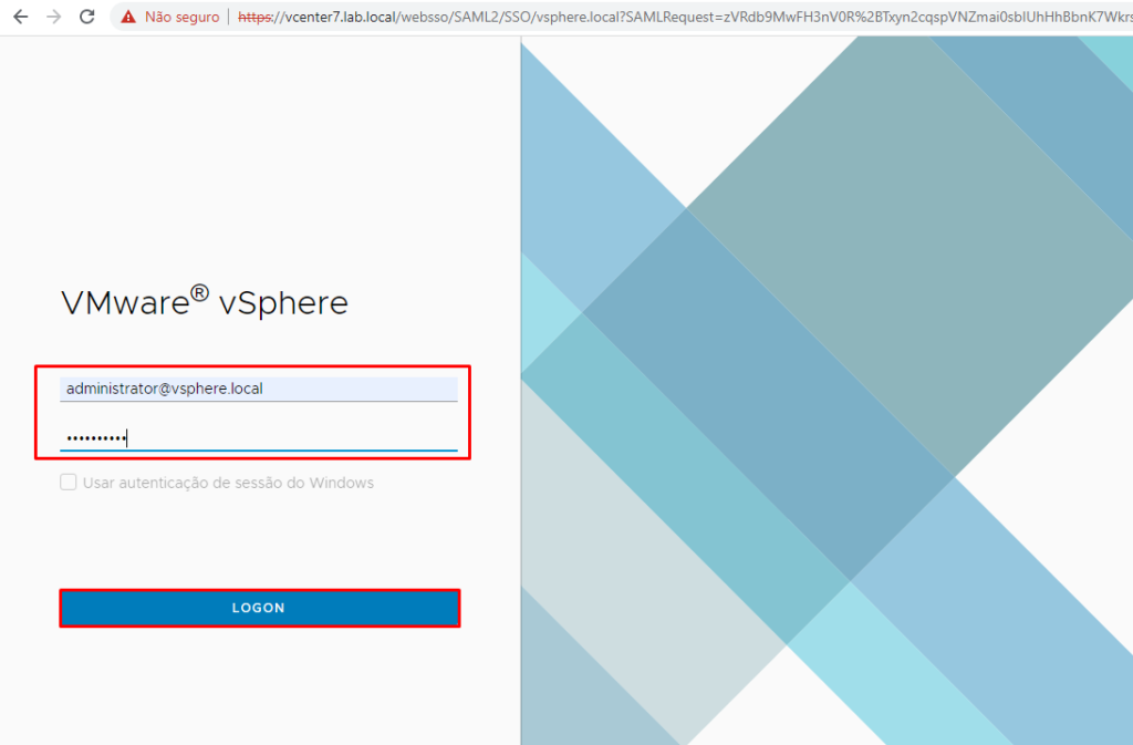
Power on the vCenter 7 Virtual Machine and access the vSphere Client. Due to the vCenter Server having a lot of services, the vSphere Client interface can take a few minutes to be available.
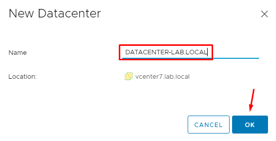
We should create the Datacenter object on the vSphere Client. In this lab, the Datacenter name is “DATACENTER-LAB.LOCAL”:
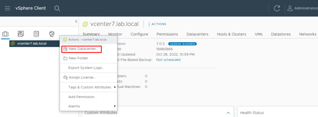
Right Click on the vCenter Server name and then click on “New Datacenter”:
Type the Datacenter name and click on “OK”:
The next step is to add each ESXi host to this Datacenter object.
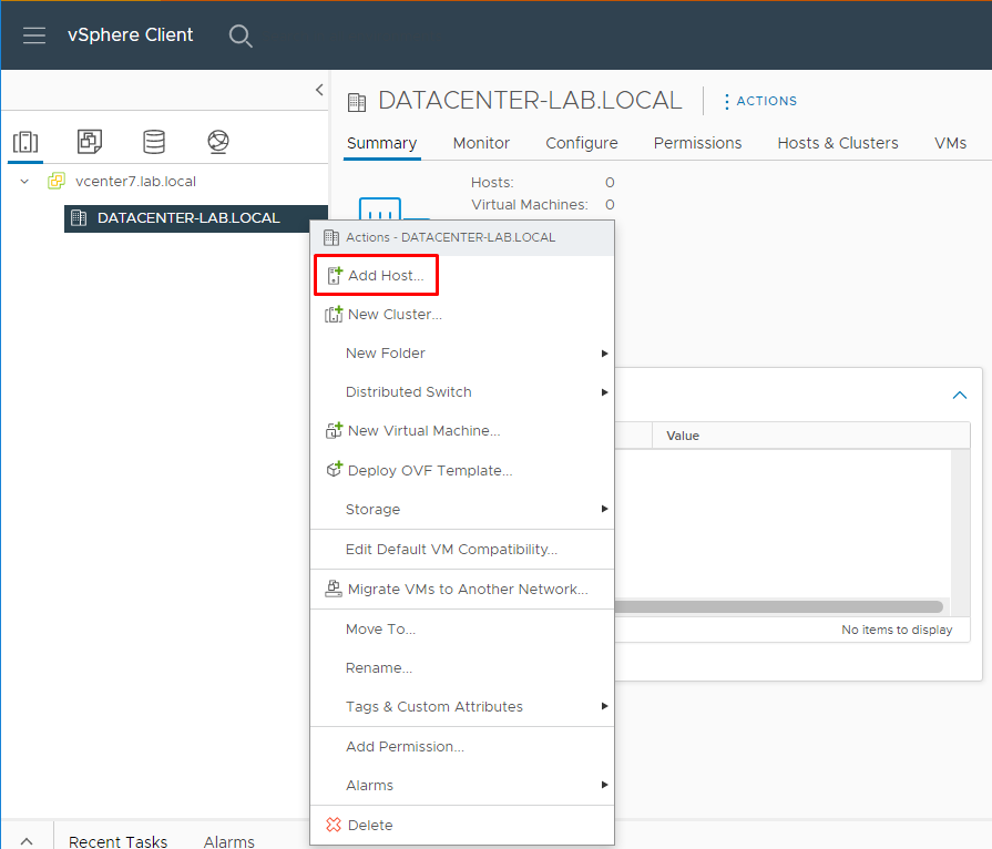
Select the Datacenter object, right-click on it and click on “Add Host”. A wizard will start to help in the add node process:
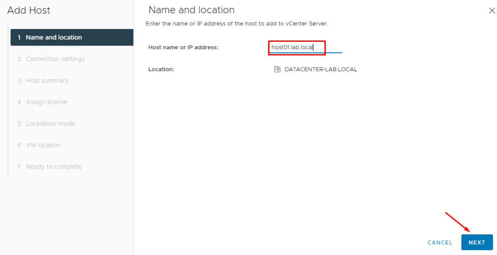
Type the hostname or IP address of the ESXi host. In this case, we are adding the ESXi host “host01.lab.local”:
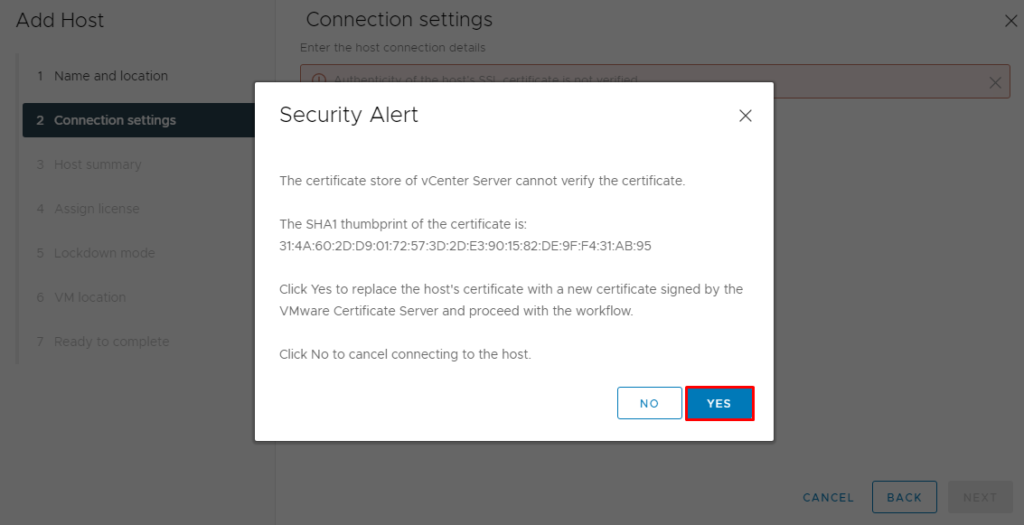
Confirm the Security Alert and follow the wizard:
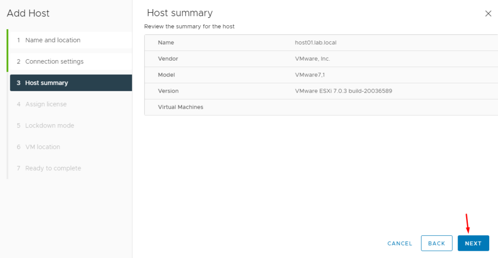
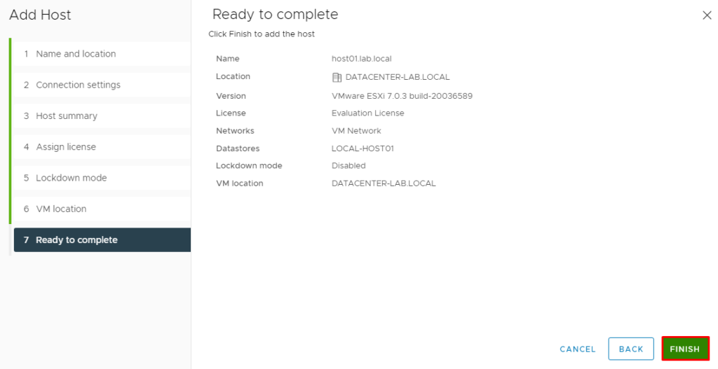
Click on “FINISH” to finish the host add process:
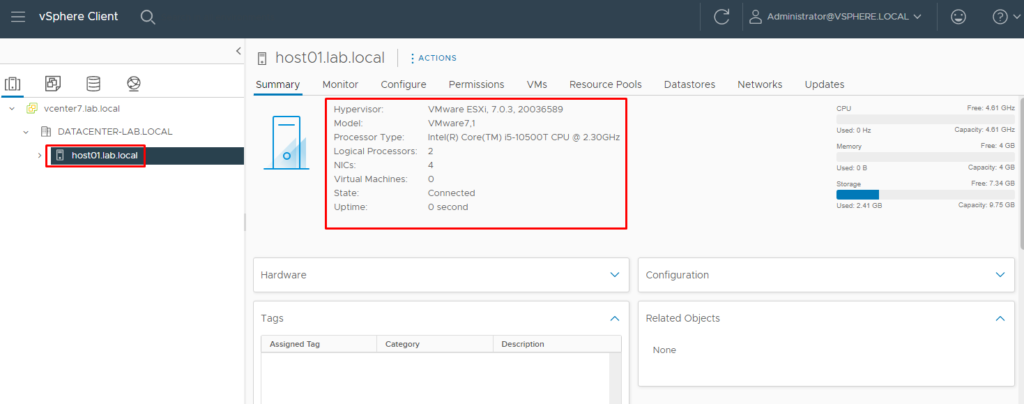
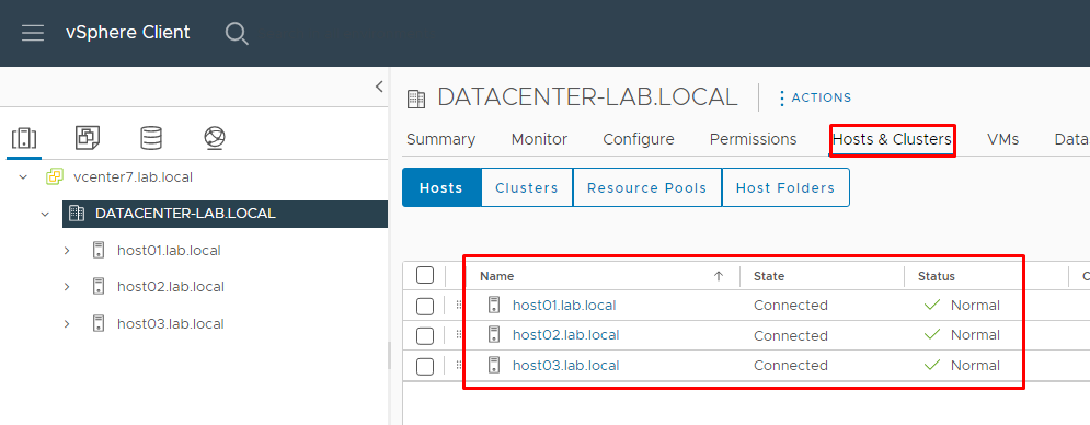
Repeat the same steps to add the ESXi “‘host02” and the ESXi “host03”:
Create a Distributed Switch and Port Groups
Create the DVS (Distributed Port Group) and all DPG (Distributed Port Groups) that we are using in this lab (we recommend doing it before creating a cluster):
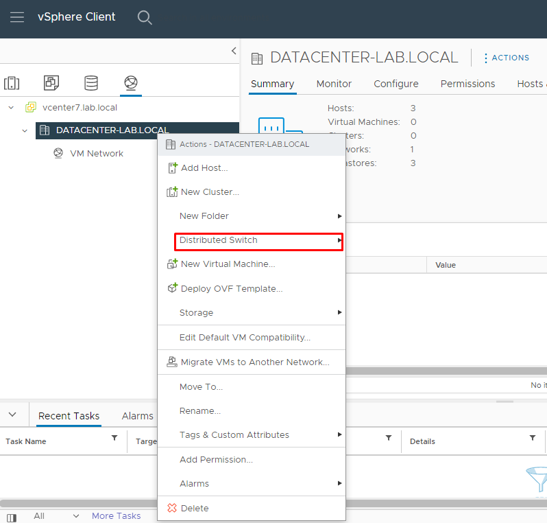
Select the Distributed Switch and right-click on Distributed Switch –> New Distributed Switch:
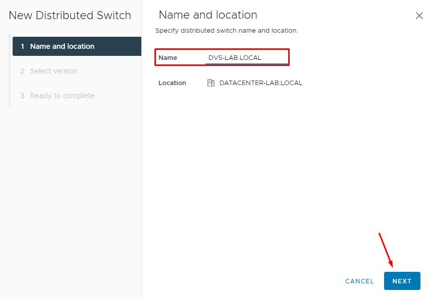
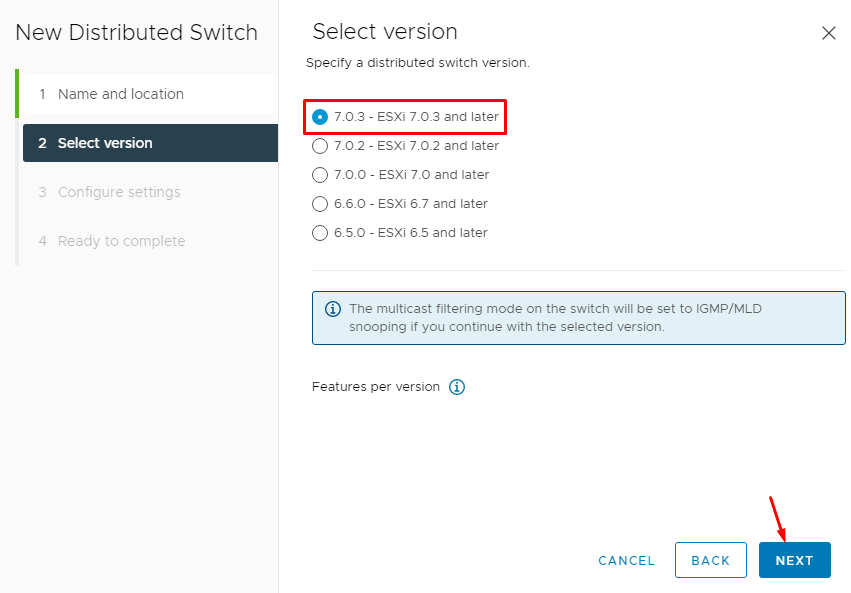
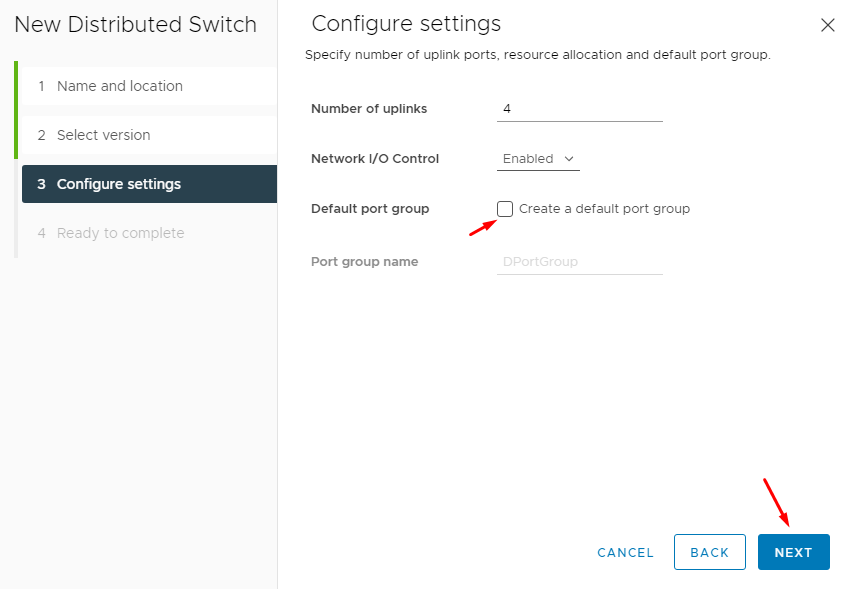
Unmark the option “Create a default port group”:
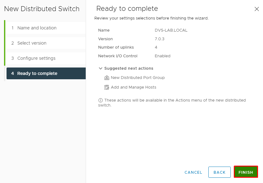
Click on “Finish” to finish the Distributed Switch creation wizard:
After that, we will create the Distributed Port Groups.
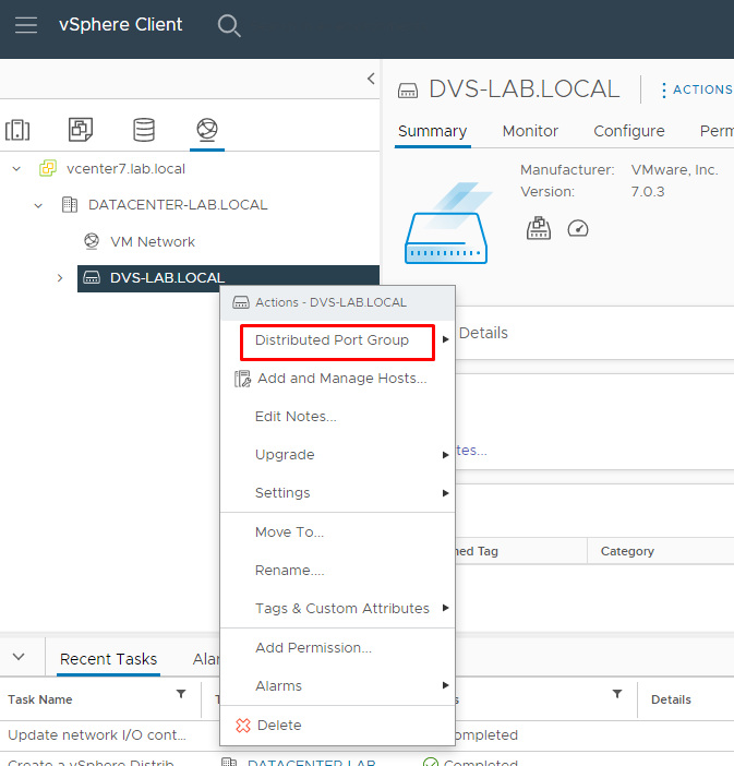
Select the Distributed Switch and right click on it, and select “Distributed Port Group” –> New Distributed Port Group:
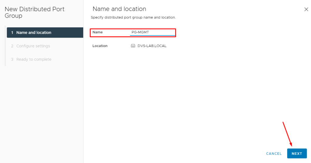
Type the name of the Distributed Port Group.
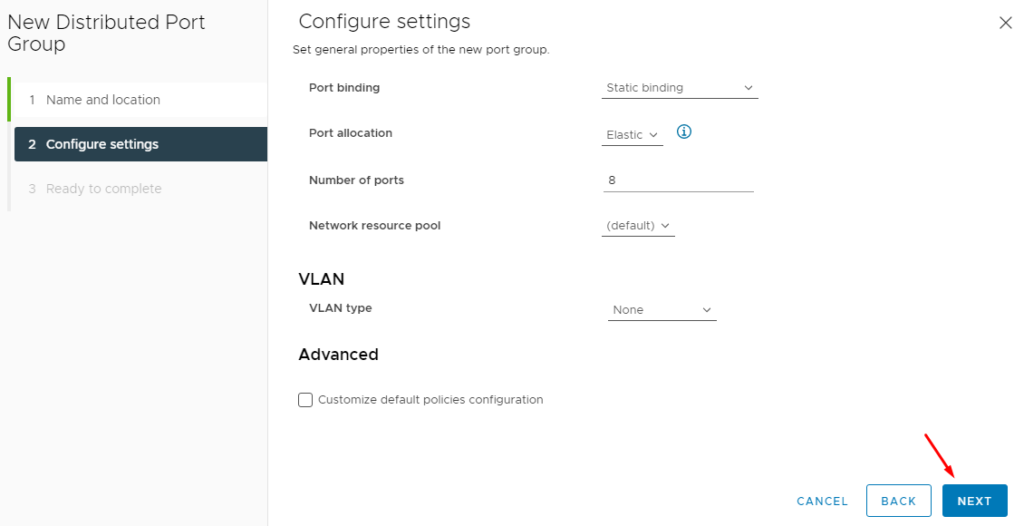
In this case, we are creating the PG “PG-MGMT”, dedicated to the device management:
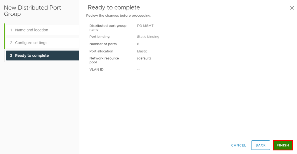
Click on “FINISH” to finish the Distributed Port Group wizard:
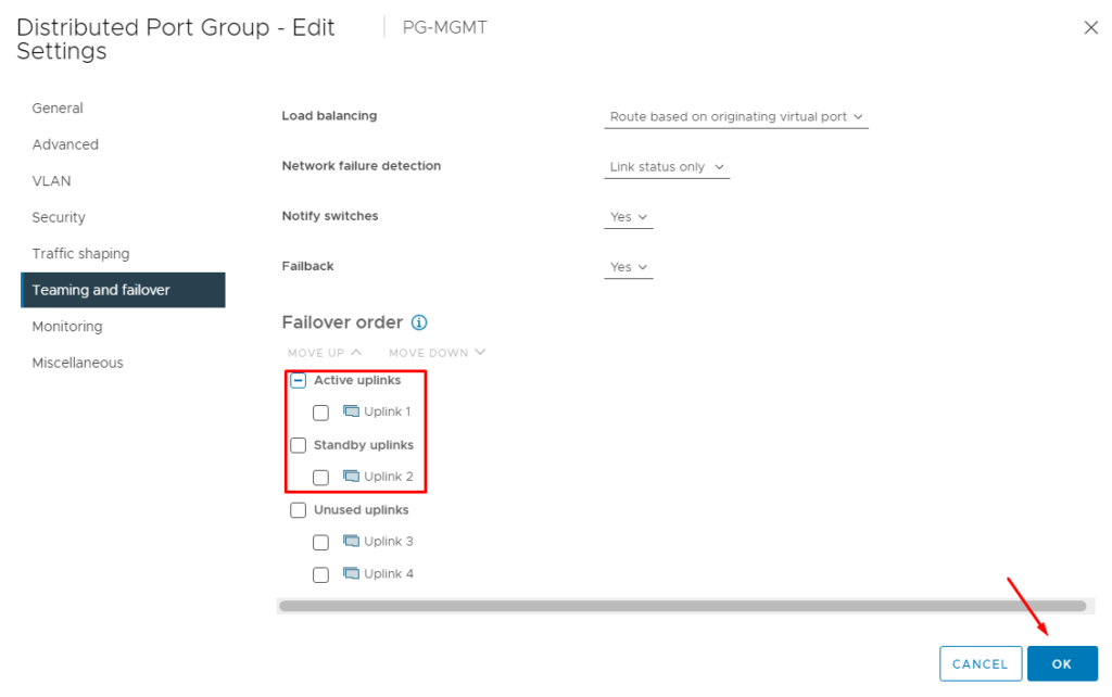
Edit this Distributed Port Group and select the tab “Teaming and failover”. On Failover order, mark the “Uplink 1” as Active Uplinks and mark the “Uplink 2” as Standby Uplinks.
Mark the “Uplink 3” and “Uplink 4” as Unused Uplinks:
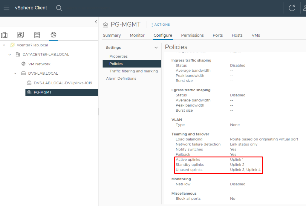
Here, we can confirm the Teaming and failover configuration for this PG:
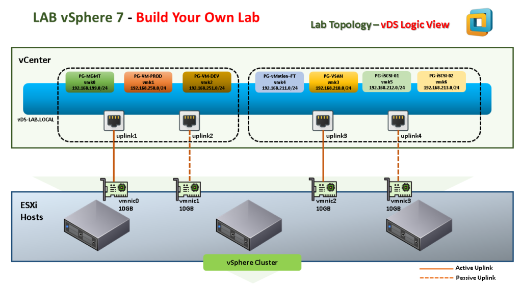
Create the other Distributed Port Groups such as demonstrated in the topology below.
Don’t forget to configure the Teaming and policy option for each Port Group, according to the topology:
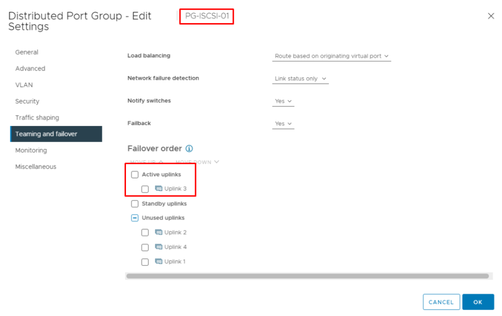
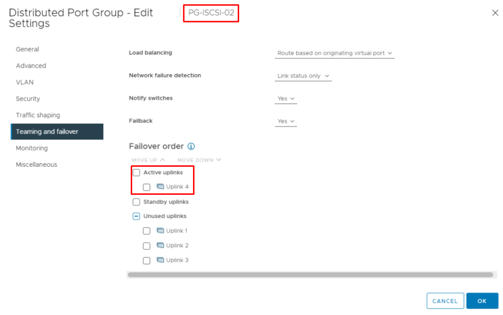
Note: For the PG “PG-ISCSI-01” and the PG “PG-ISCSI-02”, the Teaming and failover are a little bit different. We only use one Uplink as Active Uplink and the other as set with Unused Uplink.
For the PG “PG-ISCSI-01” we are using the Uplink3 as Active:
For the PG “PG-ISCSI-02” we are using the Uplink4 as Active:
Add all ESXi hosts into DVS
Add all ESXi hosts to Distributed Switch and create the VMkernels as necessary according to the network topology:
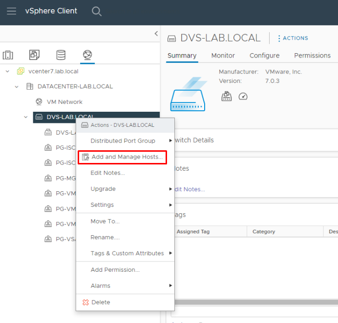
On the Networking tab, select the Distributed Switch, right-click on the Distributed Switch, and then click on “Add and Manage Hosts”:
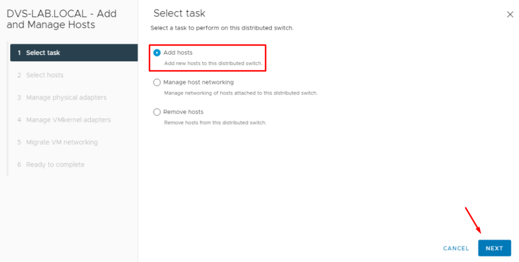
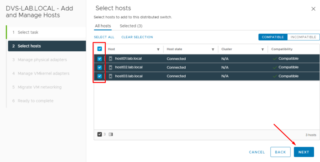
Select all ESXi hosts and click on NEXT:
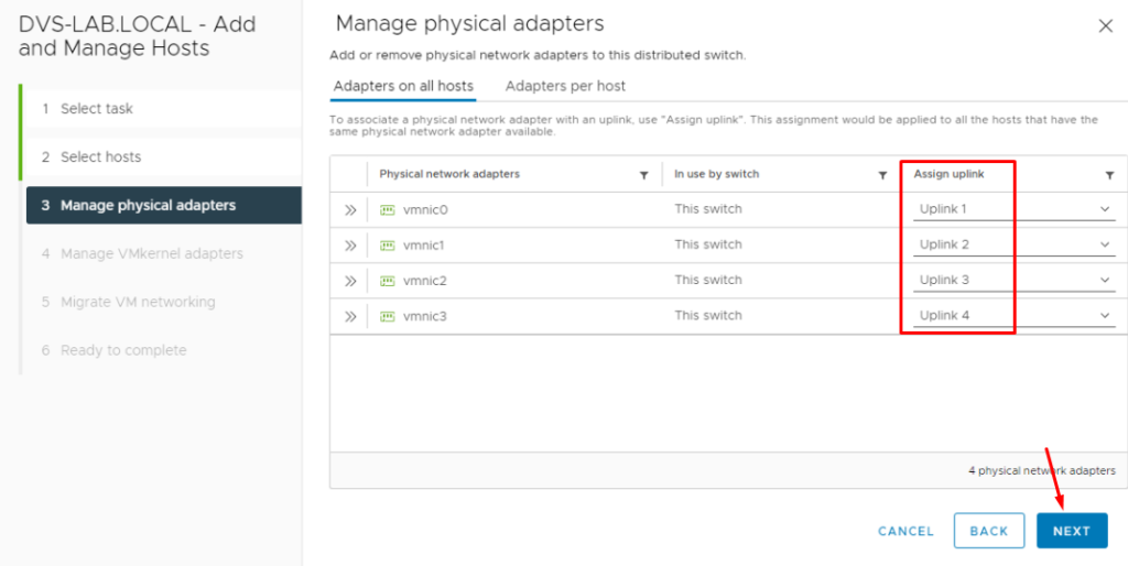
On Manage physical adapters page, we need to assign each vmnic interface to the one uplink.
vmnic0 –> uplink1
vmnic1 –> uplink2
vmnic2 –> uplink3
vmnic3 –> uplink4
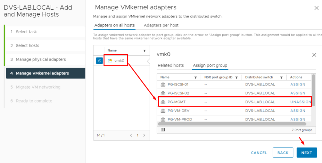
On the Manage VMkernel adapters page, select the vmk0 and then assign this VMkernel to the Distributed Port Group “PG-MGMT”.
Here, the VMkernel interface vmk0 will be migrated from the Standard Switch to the Distributed Switch:
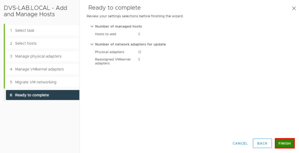
Click on “Finish” to finish the add host wizard:
Now, when we opened the Virtual Switches tab on the ESXi host, we can see the Distributed Switch “DVS-LAB.LOCAL” and also we can see the Distributed Port Group “PG-MGMT”:
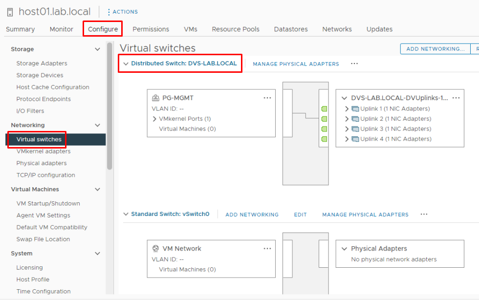
The Standard Switch “vSwitch0” will not be used, so, we can remove this Standard Switch:
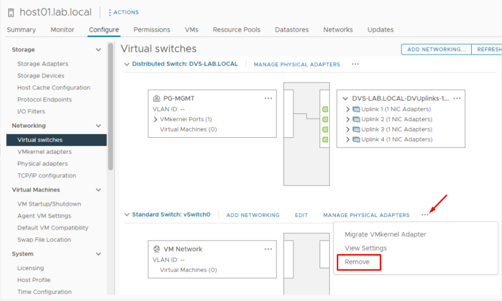
Note: Remove the Standard Switch “vSwitch0” from the ESXi host02 and the ESXi host03.
Create the VMkernel Interfaces
Create the VMkernel interface for each Port Group, except for the Port Group “PG-MGMT” (here we already have the VMkernel).
Note: In this lab, the VMkernel for the Port Groups “PG-VM-PROD” and “PG-VM-DEV” are optional to create. It is because, in some environments, these Port Groups are not necessary. So, we will not create these Port Groups here.
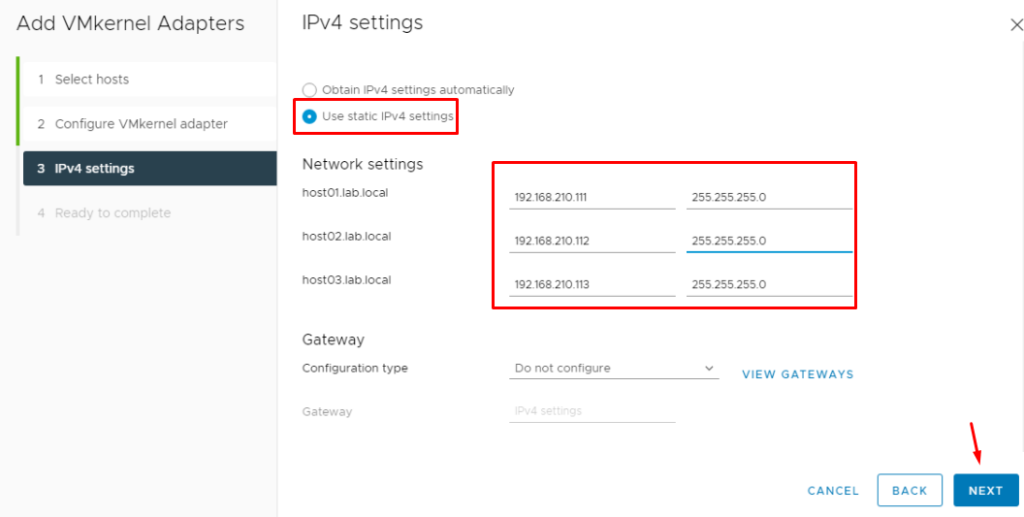
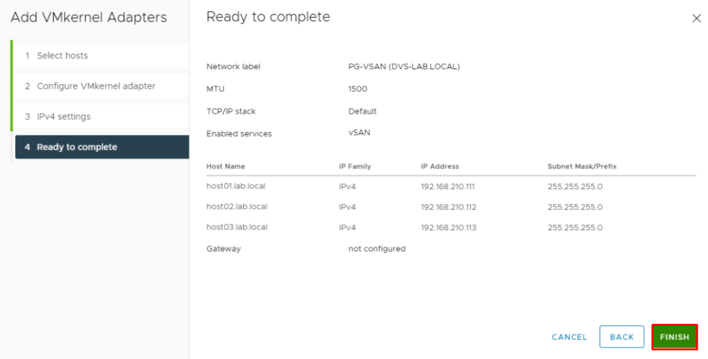
To create the VMkernel for vSAN, follow the steps below – We will not use the vSAN service now, but it is a good idea to create this VMkernel now:
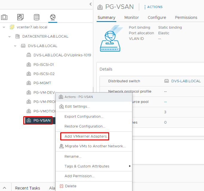
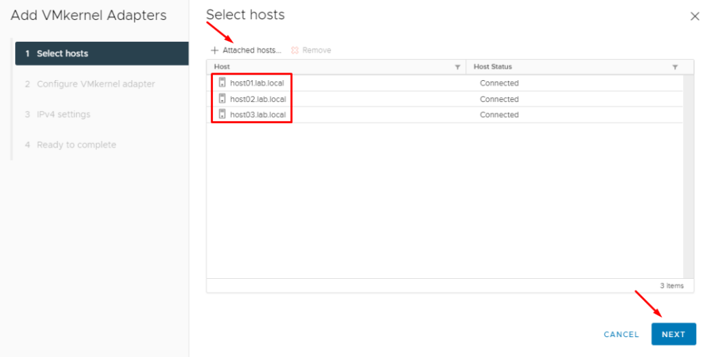
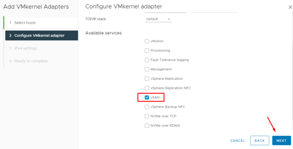
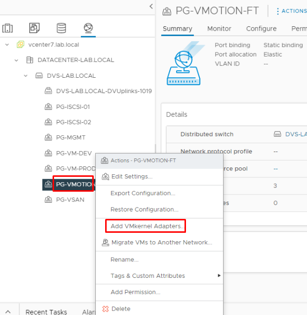
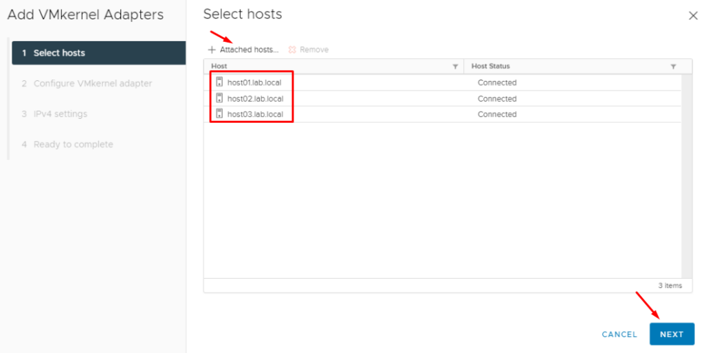
To create the VMkernel for vMotion, follow the steps below:
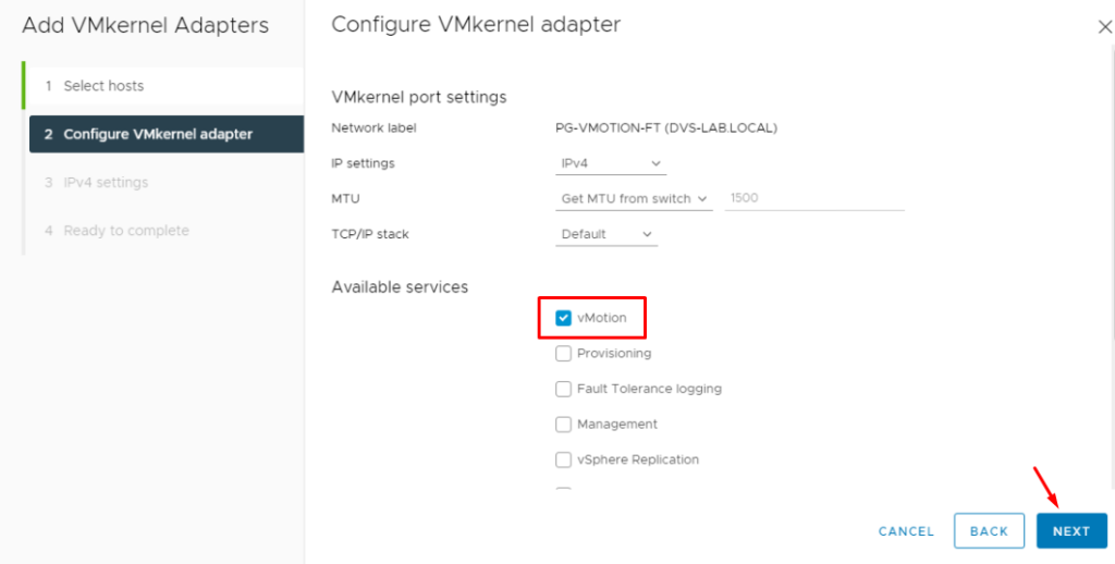
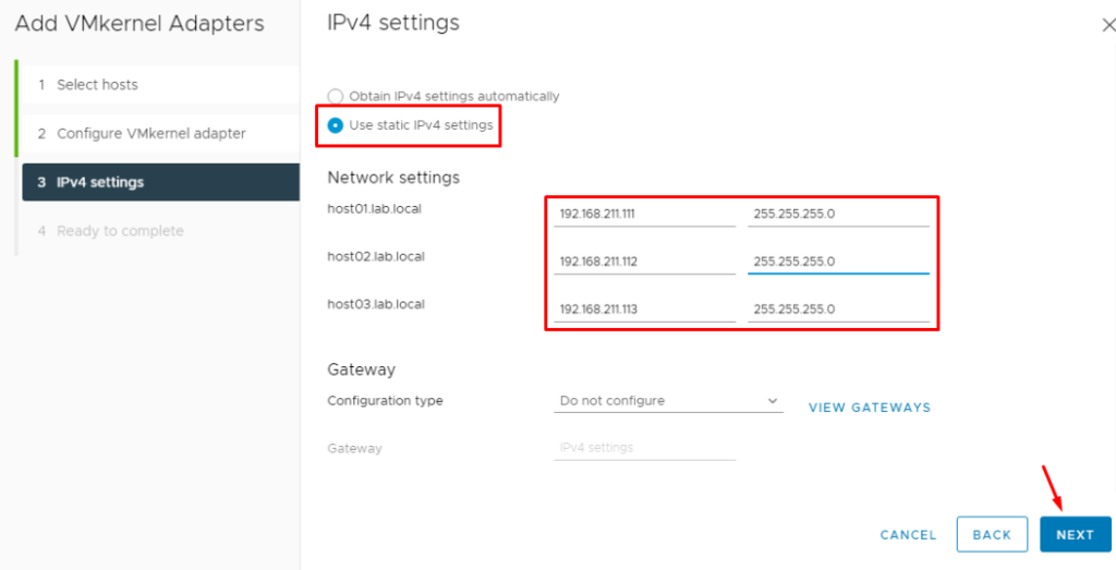
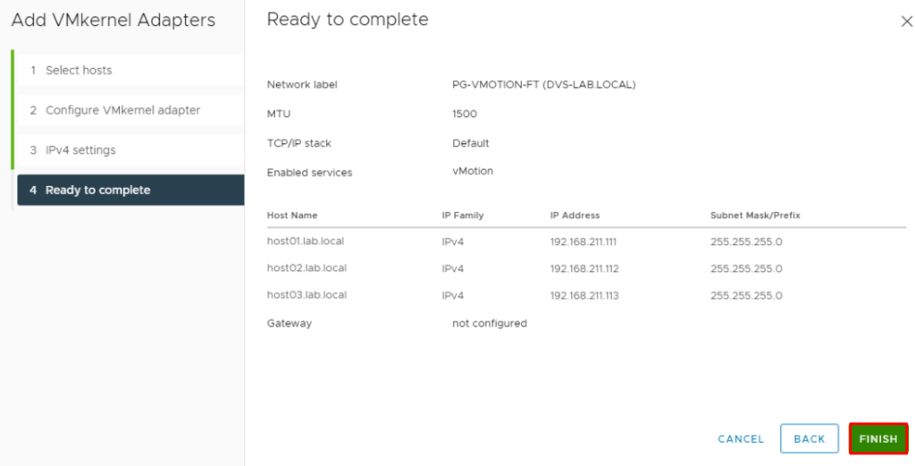
Note: Repeat the same steps to create the VMkernel for Port Group “PG-ISCSI-01” and “PG-ISCSI-02”. For these PGs, it doesn’t necessary to associate with any Services (like vMotion or vSAN, for example).
Configure the iSCSI service on each ESXi host
- Configure the iSCSI service on each ESXi host present on the vSphere Cluster.
The iSCSI configuration consists of adding the iSCSI Software Adapter (vmhba65) and adding the iSCSI Target. After it, all ESXi hosts will “see” the LUNs that are provided by TrueNAS.
Select the ESXi host –> Configure –> Storage Adapters –> Add Software Adapter –> Add iSCSI Adapter:
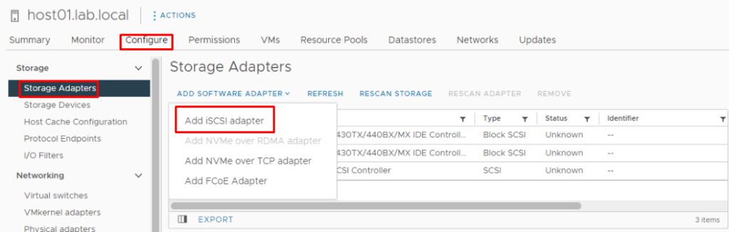
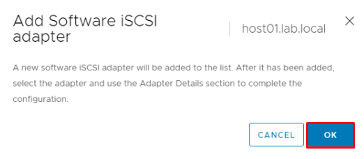
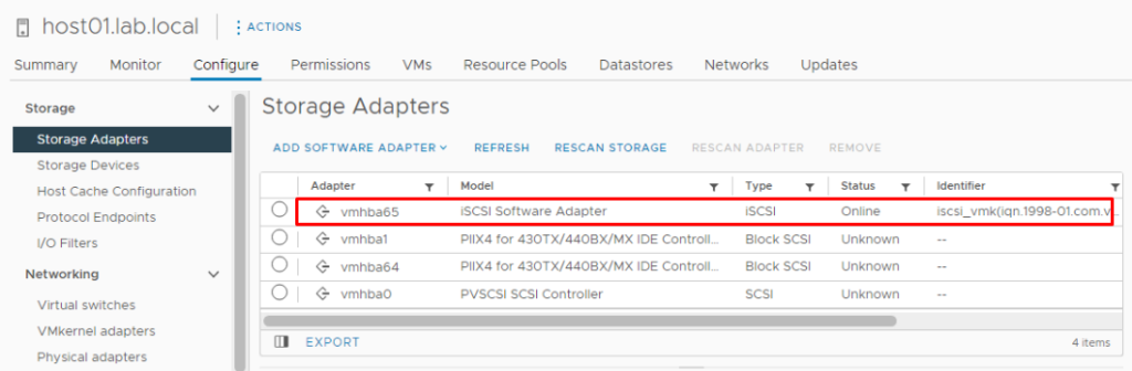
Observe that the adapter “vmhba65” was added:
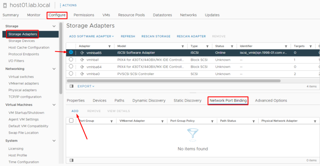
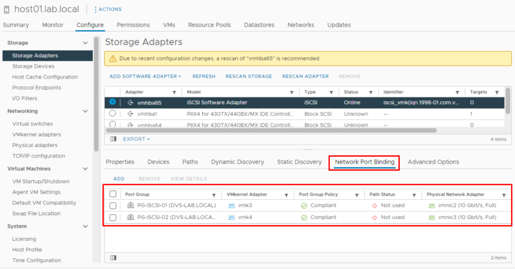
Select this iSCSI Adaptor, click on the Network Port Binding tab, and then click on “ADD”:
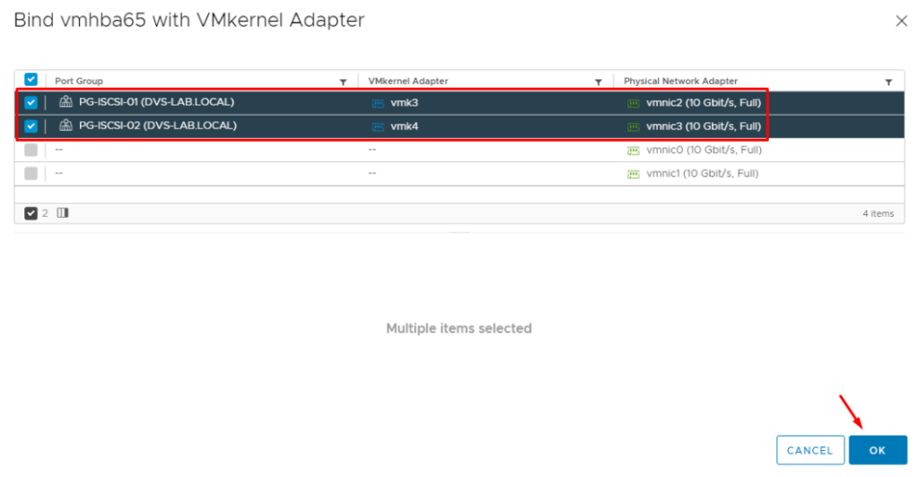
Select both Port Groups reserved to use on the iSCSI networking:
After it, both Port Groups are showing on this tab:
The next step is to add the iSCSI Target.
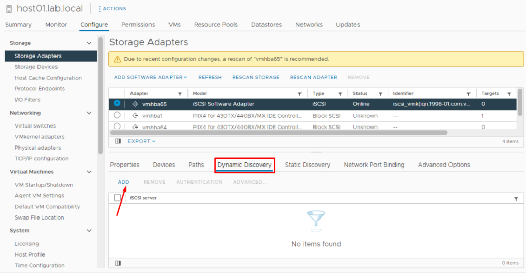
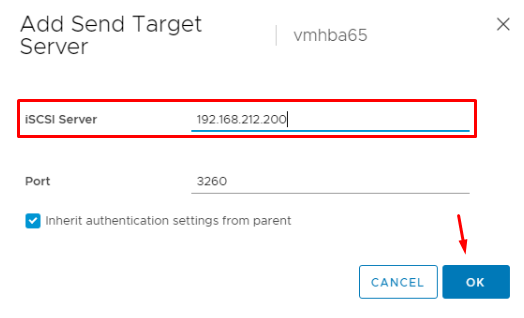
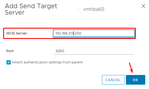
On Dynamic Discovery, click on “ADD” and type both IP addresses of the Target (iSCSI Server /TrueNAS):
The first IP address of the iSCSI Target:
The second IP address of the iSCSI Target:
To apply the configurations is necessary to click on “RESCAN ADAPTER”:
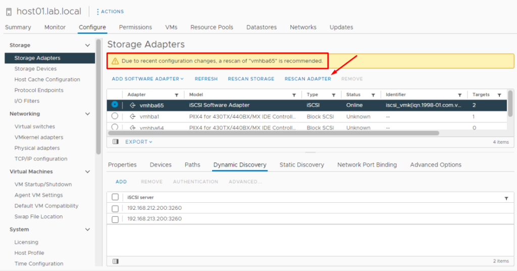
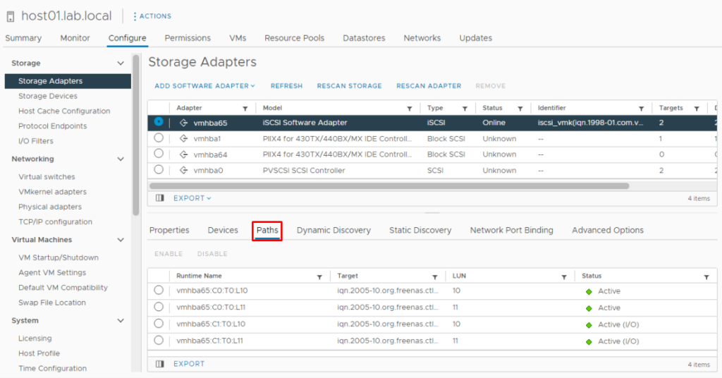
Now, on the Paths tab, we can see all paths to the iSCSI Target:
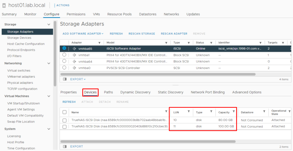
And also we can see the iSCSI devices (LUN 10 and LUN 11):
Note: Repeat these steps to the ESXi host02 and the ESXi host03.
Create the Datastores using the iSCSI devices
Create the Datastores using the iSCSI devices.
On the Datastores, select Storage –> Add Storage:
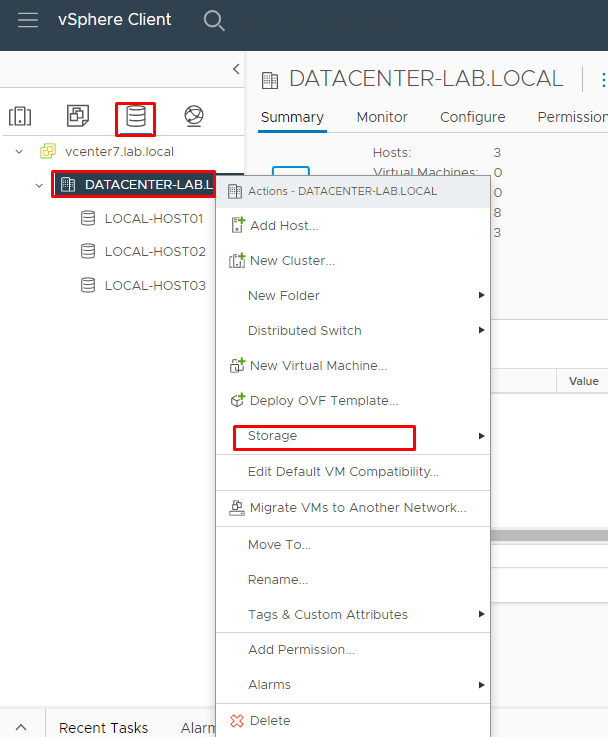
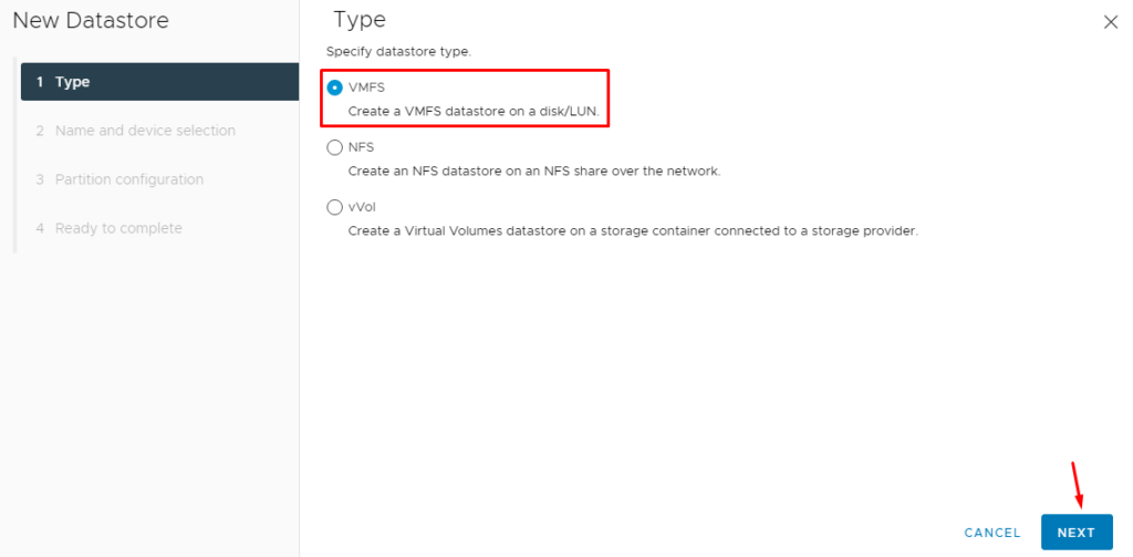
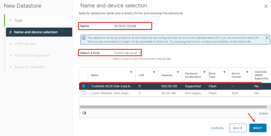
Type the Datastore name, select a host and select the disk to use in this Datastore:
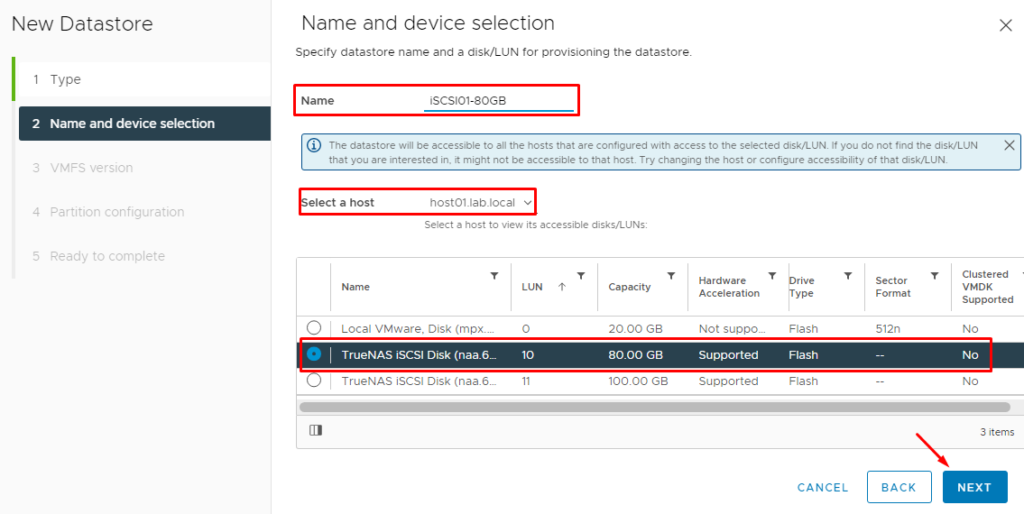
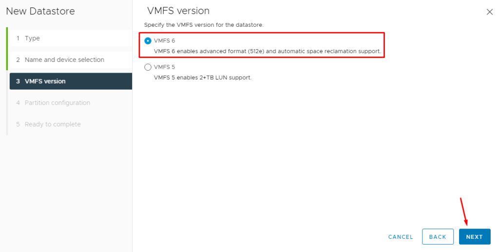
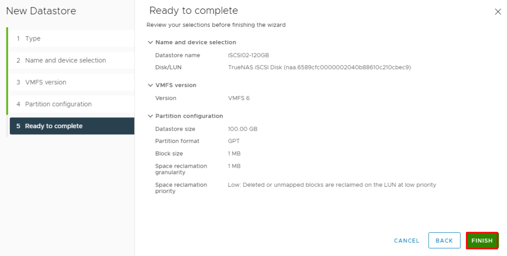
Click on “Finish” to finish the Datastore creation wizard:
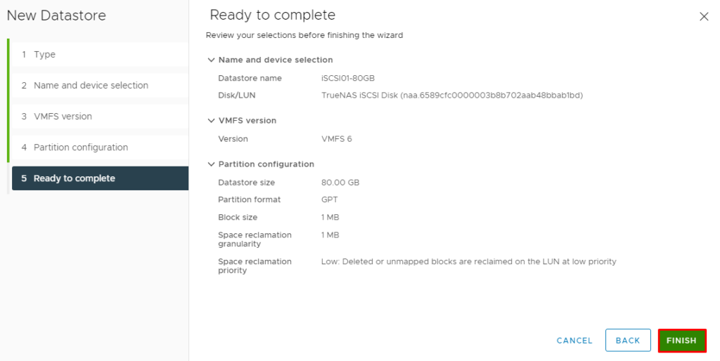
Repeat the same steps to create the other Datastore:
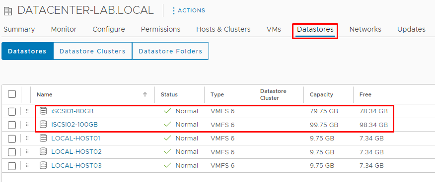
After it, when we are selecting the Datastores tab, we can see both Datastores that we created:
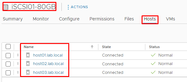
Selecting the “iSCSI01-80GB” Datastore, on the Hosts tab, we can see that all ESXi hosts can access this Datastore:
Create the cluster object and migrate all ESXi hosts into the cluster
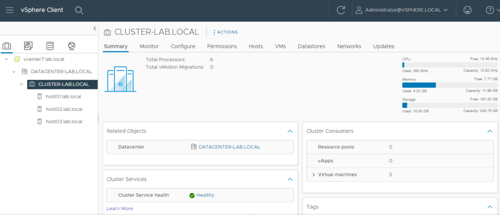
Create the Cluster object and migrate all ESXi hosts into this Cluster. After creating the Cluster, select each ESXi host and “drag-an-drop” it on the Cluster name.
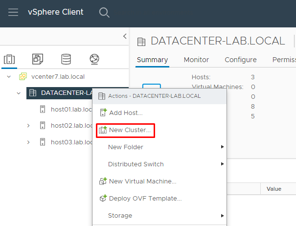
Select the Datacenter name, right-click on it, and select “New Cluster”:
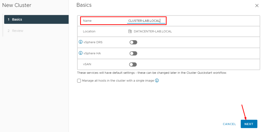
Type the Cluster name. In this lab, the Cluster name is “CLUSTER-LAB.LOCAL”:
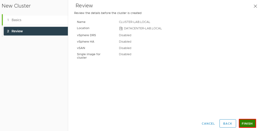
Click on “Finish” to create the Cluster object:
Here, our cluster is completed 🙂
We can create Virtual Machines and enable other vSphere Services such as HA (High Availability) and DRS (Distributed Resource Schedule), for example:
Note: To get details about the vSphere HA and vSphere DRS working together, click on the link below:
